Computer Structure: Structural Units/Components

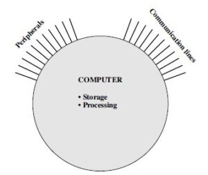
- This is the simplest possible depiction of a computer
- The computer interacts in some fashion with its external environment
- In general, all of its linkages to the external environment can be classified as peripheral devices or communication lines
- There are four main structural components:
- Central processing unit (CPU): Controls the operation of the computer and performs its data processing functions
– Often simply referred to as processor
- Main memory: Stores data
- I/O: Moves data between the computer and its external environment
- System interconnection: Some mechanism that provides for communication among CPU, main memory, and I/O
- A common example of system interconnection is by means of a system bus, consisting of a number of conducting wires to which all the other components attach.
Top-Level Structure

Processor Design & Instruction Execution
Overview
- At a top level, a computer consists of CPU (central processing unit), memory, and I/O components, with one or more modules of each type
- These components are interconnected in some fashion to achieve the basic function of the computer
- At a top level, we can describe a computer system by
- Describing the external behavior of each component—that is, the data and control signals that it exchanges with other components; and
- Describing the interconnection structure and the controls required to manage the use of the interconnection structure
- Virtually all contemporary computer designs are based on concepts developed by John von Neumann at the Institute for Advanced Studies, Princeton
- Such a design is referred to as the von Neumann architecture and is based on three key concepts:
- Data and instructions are stored in a single read–write memory
- The contents of this memory are addressable by location, without regard to the type of data contained there
- Execution occurs in a sequential fashion (unless explicitly modified) from one instruction to the next
Types of Programming
- Two types:
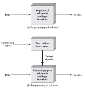
- Hardwired Programming
- Software Programming

- Figure b indicates two major components of the system: an instruction interpreter and a module of general-purpose arithmetic and logic functions
- These two constitute the CPU
- Several other components are needed to yield a functioning computer
- Data and instructions must be put into the system and results must be shown in realizable forms
- We need I/O module for that
- A place is also needed for storing the data and instructions
- We need Memory for that
GP Processor

- Figure illustrates these top-level components
- CPU exchanges data with memory
- For this purpose, it typically makes use of two internal (to the CPU) registers: a memory address register (MAR), which specifies the address in memory for the next read or write, and a memory buffer register (MBR), which contains the data to be written into memory or receives the data read from memory
- Similarly, an I/O address register (I/OAR) specifies a particular I/O device
- An I/O buffer (I/OBR) register is used for the exchange of data between an I/O module and the CPU
Function of GP Processor
- The basic function performed by a computer is execution of a program, which consists of a set of instructions stored in memory
- In its simplest form, instruction processing consists of two steps:
- The processor reads (fetches) instructions from memory one at a time and executes each instruction
- Program execution consists of repeating the process of instruction fetch and instruction execution
- The processing required for a single instruction is called an instruction cycle
Instruction Fetch and Execute

- In a typical processor, a register called the program counter (PC) holds the address of the instruction to be fetched next
- Unless told otherwise, the processor always increments the PC after each instruction fetch so that it will fetch the next instruction in sequence
- The fetched instruction is loaded into a register in the processor known as the instruction register (IR)
- The instruction contains bits that specify the action the processor is to take
- In general, these actions fall into four categories:
- Processor-memory: Data may be transferred from processor to memory or from memory to processor
- Processor-I/O: Data may be transferred to or from a peripheral device by transferring between the processor and an I/O module
- Data processing: The processor may perform some arithmetic or logic operation on data
- Control: An instruction may specify that the sequence of execution be altered
- For example, the processor may fetch an instruction from location 149, which specifies that the next instruction be from location 182. The processor will remember this fact by setting the program counter to 182
- Thus, on the next fetch cycle, the instruction will be fetched from location 182 rather than 150
A Hypothetical Processor

The above figure illustrates a partial program execution, showing the relevant portions of memory and processor registers.1 The program fragment shown adds the contents of the memory word at address 940 to the contents of the memory word at address 941 and stores the result in the latter location. Three instructions, which can be described as three fetch and three execute cycles, are required:
- The PC contains 300, the address of the first instruction. This instruction (the value 1940 in hexadecimal) is loaded into the instruction register IR and the PC is incremented. Note that this process involves the use of a memory address register (MAR) and a memory buffer register (MBR). For simplicity, these intermediate registers are ignored.
- The first 4 bits (first hexadecimal digit) in the IR indicate that the AC is to be loaded. The remaining 12 bits (three hexadecimal digits) specify the address (940) from which data are to be loaded.
- The next instruction (5941) is fetched from location 301 and the PC is incremented.
- The old contents of the AC and the contents of location 941 are added and the result is stored in the AC.
- The next instruction (2941) is fetched from location 302 and the PC is incremented.
- The contents of the AC are stored in location 941.
Instruction Cycle State Diagram

For any given instruction cycle, some states may be null and others may be visited more than once. The states can be described as follows:
- Instruction address calculation (iac): Determine the address of the next instruction to be executed. Usually, this involves adding a fixed number to the address of the previous instruction. For example, if each instruction is 16 bits long and memory is organized into 16-bit words, then add 1 to the previous address. If, instead, memory is organized as individually addressable 8-bit bytes, then add 2 to the previous address.
- Instruction fetch (if): Read instruction from its memory location into the processor.
- Instruction operation decoding (iod): Analyze instruction to determine type of operation to be performed and operand(s) to be used.
- Operand address calculation (oac): If the operation involves reference to an operand in memory or available via I/O, then determine the address of the operand.
- Operand fetch (of): Fetch the operand from memory or read it in from I/O.
- Data operation (do): Perform the operation indicated in the instruction.
- Operand store (os): Write the result into memory or out to I/O.

0 Comments