Three Dimensional Graphics
The 2D can show two-dimensional objects. Like the Bar chart, pie chart, graphs. But some more natural objects can be represented using 3D. Using 3D, we can see different shapes of the object in different sections. In 3D when a translation is done we need three factors for rotation also, it is a component of three rotations. Each can be performed along any three Cartesian axis. In 3D also we can represent a sequence of transformations as a single matrix. Computer Graphics uses CAD. CAD allows manipulation of machine components which are 3 Dimensional. It also provides automobile bodies, aircraft parts study. All these activities require realism. For realism 3D is required. In the production of a realistic 3D scene from 2D is tough. It require three dimension, i.e., depth.
3D Geometry
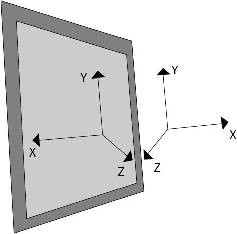
Three dimension system has three axis x, y, z. The orientation of a 3D coordinate system is of two types. Right-handed system and left-handed system. In the right -handed system thumb of right- hand points to positive z-direction and left- hand system thumb point to negative two directions. Following figure show right-hand orientation of the cube.
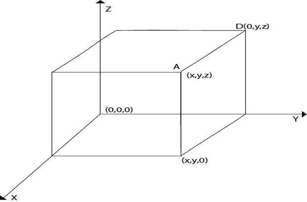
Using right-handed system co-ordinates of corners A, B, C, D of the cube
Point A x, y, z
Point B x, y, 0
Point C 0, y, 0
Point D 0, y, z
Producing realism in 3D:
The three-dimensional objects are made using computer graphics. The technique used for two Dimensional displays of three Dimensional objects is called projection. Several types of projection are available, i.e.,
- Parallel Projection
- Perspective Projection
- Orthographic Projection
1. Parallel Projection:
In this projection point on the screen is identified within a point in the three-dimensional object by a line perpendicular to the display screen. The architect Drawing, i.e., plan, front view, side view, elevation are nothing but lines of parallel projections.
2. Perspective Projection:
This projection has a property that it provides idea about depth. Farther the object from the viewer, smaller it will appear. All lines in perspective projection converge at a center point called as the center of projection.
3. Orthographic Projection: It is simplest kind of projection. In this, we take a top, bottom, side view of the object by extracting parallel lines from the object.
Three Dimensional Models
The techniques for generating different images of a solid object depend upon the type of object. Two viewing techniques are available for viewing three-dimensional objects.
- Geometry: It is concerned with measurements. Measurement is the location of a point concerning origin or dimension of an object.
- Topological Information: It is used for the structure of a solid object. It is mainly concerned with the formation of polygons with the help of points of objects or the creation of the object with polygons.
Three Dimensional Transformations
The geometric transformations play a vital role in generating images of three Dimensional objects with the help of these transformations. The location of objects relative to others can be easily expressed. Sometimes viewpoint changes rapidly, or sometimes objects move in relation to each other. For this number of transformation can be carried out repeatedly.
Translation
It is the movement of an object from one position to another position. Translation is done using translation vectors. There are three vectors in 3D instead of two. These vectors are in x, y, and z directions. Translation in the x-direction is represented using Tx. The translation is y-direction is represented using Ty. The translation in the z- direction is represented using Tz.
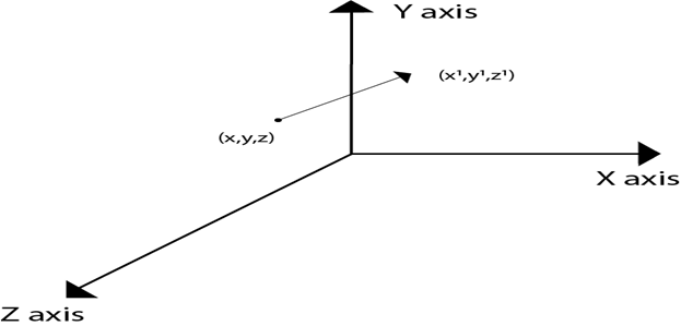
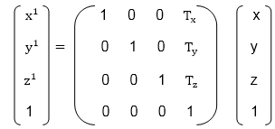
If P is a point having co-ordinates in three directions (x, y, z) is translated, then after translation its coordinates will be (x1 y1 z1) after translation. Tx Ty Tz are translation vectors in x, y, and z directions respectively.
x1=x+ Tx
y1=y+Ty
z1=z+ Tz
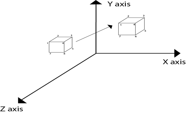
Three-dimensional transformations are performed by transforming each vertex of the object. If an object has five corners, then the translation will be accomplished by translating all five points to new locations. Following figure 1 shows the translation of point figure 2 shows the translation of the cube.
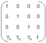
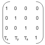
Matrix for translation
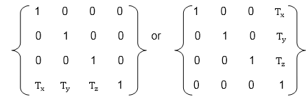
Matrix representation of point translation
Point shown in fig is (x, y, z). It become (x1,y1,z1) after translation. Tx Ty Tz are translation vector.
Example:
A point has coordinates in the x, y, z direction i.e., (5, 6, 7). The translation is done in the x-direction by 3 coordinate and y direction. Three coordinates and in the z- direction by two coordinates. Shift the object. Find coordinates of the new position.
Solution: Co-ordinate of the point are (5, 6, 7)
Translation vector in x direction = 3
Translation vector in y direction = 3
Translation vector in z direction = 2
Translation matrix is
Multiply co-ordinates of point with translation matrix
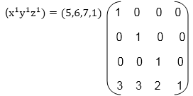
= [5+0+0+30+6+0+30+0+7+20+0+0+1] = [8991]
x becomes x1=8
y becomes y1=9
z becomes z1=9
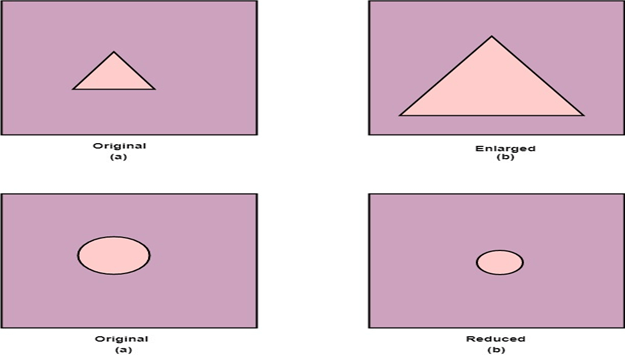
Scaling
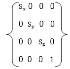
Scaling is used to change the size of an object. The size can be increased or decreased. The scaling three factors are required Sx Sy and Sz.
Sx=Scaling factor in x- direction
Sy=Scaling factor in y-direction
Sz=Scaling factor in z-direction
Matrix for Scaling
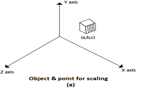
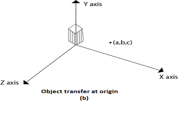
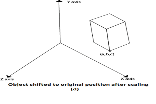
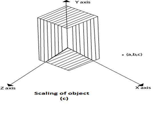
Scaling of the object relative to a fixed point
Following are steps performed when scaling of objects with fixed point (a, b, c). It can be represented as below:
- Translate fixed point to the origin
- Scale the object relative to the origin
- Translate object back to its original position.
In figure (a) point (a, b, c) is shown, and object whose scaling is to done also shown in steps in fig (b), fig (c) and fig (d).
Scaling
Scaling is used to change the size of an object. The size can be increased or decreased. The scaling three factors are required Sx Sy and Sz.
Sx=Scaling factor in x- direction
Sy=Scaling factor in y-direction
Sz=Scaling factor in z-direction
Matrix for Scaling
Scaling of the object relative to a fixed point
Following are steps performed when scaling of objects with fixed point (a, b, c). It can be represented as below:
- Translate fixed point to the origin
- Scale the object relative to the origin
- Translate object back to its original position.
In figure (a) point (a, b, c) is shown, and object whose scaling is to done also shown in steps in fig (b), fig (c) and fig (d).
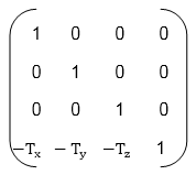
Inverse Transformations
These are also called as opposite transformations. If T is a translation matrix than inverse translation is representing using T-1. The inverse matrix is achieved using the opposite sign.
Example1: Translation and its inverse matrix
Translation matrix
Inverse translation matrix
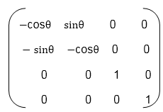
Example2: Rotation and its inverse matrix
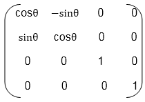
Inverse Rotation Matrix
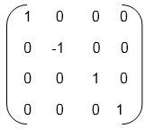
Reflection
It is also called a mirror image of an object. For this reflection axis and reflection of plane is selected. Three-dimensional reflections are similar to two dimensions. Reflection is 180° about the given axis. For reflection, plane is selected (xy,xz or yz). Following matrices show reflection respect to all these three planes.
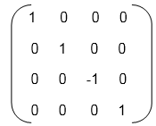
Reflection relative to XY plane
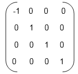
Reflection relative to YZ plane
Reflection relative to ZX plane
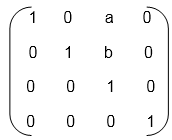
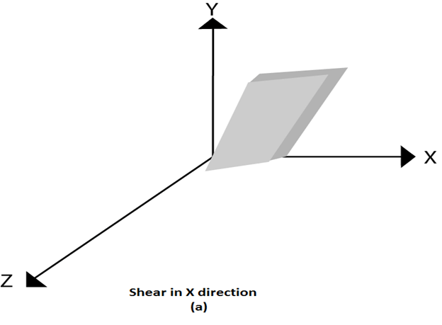
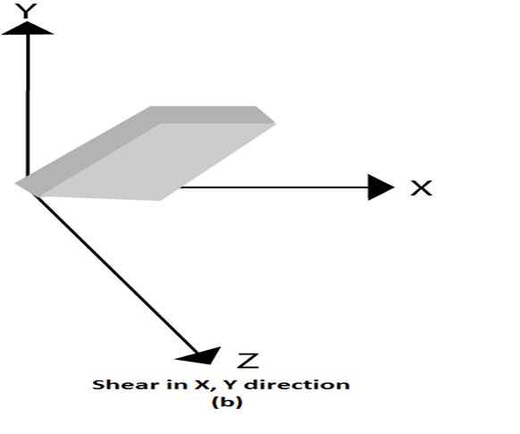
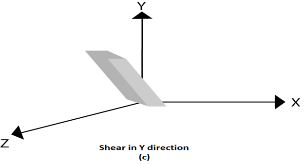
Shearing
It is change in the shape of the object. It is also called as deformation. Change can be in the x -direction or y -direction or both directions in case of 2D. If shear occurs in both directions, the object will be distorted. But in 3D shear can occur in three directions.
Matrix for shear
0 Comments