Part 5: 8085 Assembly Language Programming: Practical Algorithms, Arithmetic Routines, and Memory Manipulation
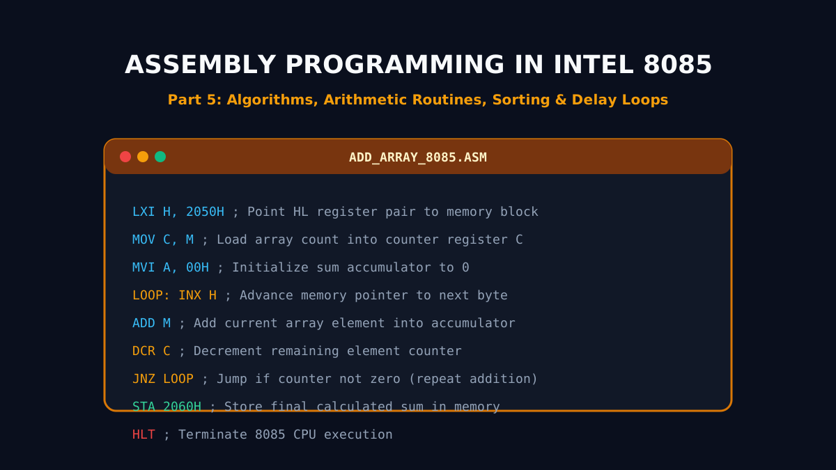
From Hardware Theory to Executable Assembly Code
Writing assembly code for the Intel 8085 demands a deep understanding of register manipulation, flag state tracking, and memory pointer arithmetic. In Part 5, we present fully documented, battle-tested assembly programs that solve classical computational tasks: multi-byte addition and subtraction with carry/borrow, finding extrema in arrays, bubble sorting blocks of numbers, and designing accurate millisecond timing delay loops.
1. Program 1: 16-Bit Addition with Carry Handling
Problem Statement: Add two 16-bit binary numbers stored at consecutive memory locations 2050H-2051H and 2052H-2053H. Store the 16-bit sum at 2054H-2055H and any generated overflow carry at 2056H.
; ====================================================================
; Program: 16-Bit Addition with Carry
; Input:  [2050H] = Low Byte 1, [2051H] = High Byte 1
;         [2052H] = Low Byte 2, [2053H] = High Byte 2
; Output: [2054H] = Sum Low,   [2055H] = Sum High, [2056H] = Carry
; ====================================================================
        LHLD 2050H     ; Load HL with 1st 16-bit number from 2050H-2051H
        XCHG           ; Exchange HL with DE (DE now holds 1st number)
        LHLD 2052H     ; Load HL with 2nd 16-bit number from 2052H-2053H
        MOV A, E       ; Move Low Byte of 1st number into Accumulator
        ADD L          ; Add Low Byte of 2nd number (A = A + L, updates CY)
        MOV L, A       ; Store Low Byte of sum temporarily into Register L
        MOV A, D       ; Move High Byte of 1st number into Accumulator
        ADC H          ; Add High Byte of 2nd number with Carry (A = A + H + CY)
        MOV H, A       ; Store High Byte of sum temporarily into Register H
        SHLD 2054H     ; Store 16-bit sum (HL) into memory 2054H-2055H
        MVI A, 00H     ; Clear accumulator
        ADC A          ; A = 0 + 0 + CY (captures final Carry into A: 00H or 01H)
        STA 2056H      ; Store final carry flag byte into 2056H
        HLT            ; Terminate execution
2. Program 2: Finding the Maximum Element in an Array
Problem Statement: An array of $N$ 8-bit unsigned integers begins at memory address 2051H. The size of the array ($N$) is stored at 2050H. Determine the maximum value in the array and save it at 2060H.
; ====================================================================
; Program: Find Maximum in an Unsigned Array
; ====================================================================
        LXI H, 2050H   ; Point HL to the array count location
        MOV C, M       ; Load array count N into counter Register C
        DCR C          ; Decrement count (N - 1 comparisons required)
        INX H          ; Increment pointer to point to 1st array element
        MOV A, M       ; Assume 1st element is the maximum (load into A)

LOOP:   INX H          ; Advance memory pointer to next candidate element
        CMP M          ; Compare Accumulator with memory operand M (A - M)
        JNC SKIP       ; If Carry = 0 (A >= M), current max remains valid, skip
        MOV A, M       ; If Carry = 1 (A < M), new maximum found! Load M into A

SKIP:   DCR C          ; Decrement remaining comparison counter
        JNZ LOOP       ; If counter != 0, continue comparison loop
        STA 2060H      ; Store the maximum value into 2060H
        HLT            ; End of program
3. Program 3: Sorting an Array in Ascending Order (Bubble Sort)
The Bubble Sort algorithm repeatedly steps through the list, compares adjacent elements, and swaps them if they are in the wrong order. For an array of size $N$, it executes $N-1$ outer passes.
; ====================================================================
; Program: 8085 Bubble Sort (Ascending Order)
; Input: [2050H] = N, [2051H...] = Array Elements
; ====================================================================
        LDA 2050H      ; Load array length N
        MOV B, A       ; B will serve as outer loop counter
        DCR B          ; Outer passes = N - 1

OUTER:  LXI H, 2051H   ; Reset HL to start of array
        MOV C, B       ; Inner loop counter C = outer counter B

INNER:  MOV A, M       ; Load current element into Accumulator
        INX H          ; Point to next adjacent element
        CMP M          ; Compare A with adjacent element M (A - M)
        JC NO_SWAP     ; If A < M, already in ascending order, no swap

        ; --- SWAP ROUTINE ---
        MOV D, M       ; Save adjacent element in Register D
        MOV M, A       ; Place larger element into memory location of next
        DCX H          ; Move pointer back to current element
        MOV M, D       ; Place smaller element into current memory location
        INX H          ; Re-advance pointer to continue pass

NO_SWAP:DCR C          ; Decrement inner loop counter
        JNZ INNER      ; Repeat inner comparison pass
        DCR B          ; Decrement outer loop counter
        JNZ OUTER      ; Repeat outer pass until fully sorted
        HLT            ; Array is sorted in-place!
4. Accurate Delay Loop Calculation in 8085
In embedded microprocessor applications, software delays are frequently used for switch debouncing, LED blinking, and serial baud rate pacing. Because each instruction requires a precise number of clock T-states, execution delay can be calculated with mathematical certainty.
Single-Register Delay Loop Analysis
LOOP: DCR C ; 4 T-states (executed COUNT times)
JNZ LOOP ; 10 T-states when branching (COUNT - 1 times), 7 T-states on last exit
For a 3.0 MHz 8085 system clock, each clock period is $T = \frac{1}{3.0 \times 10^6} \approx 0.333\,\mu\text{s}$. The total time delay $T_D$ for a count $N$ is given by:
For the maximum single-register count ($N = 255 = \text{FFH}$), total delay is:
$$T_{D,\text{max}} = 0.3333\,\mu\text{s} \times (14 \times 255 + 4) = 0.3333\,\mu\text{s} \times 3574 = 1.191\,\text{ms}$$
To achieve second-scale delays (e.g., a 1-second delay for a traffic signal), nested loops or 16-bit register pair loops (LXI B, FFFFH / DCX B) are utilized.
Summary & Next Step
In Part 6, we step out of pure assembly code to explore the practical real-world applications of microprocessors across industrial robotics, automotive electronic control units (ECUs), medical life-support systems, and consumer IoT appliances.
Related reading
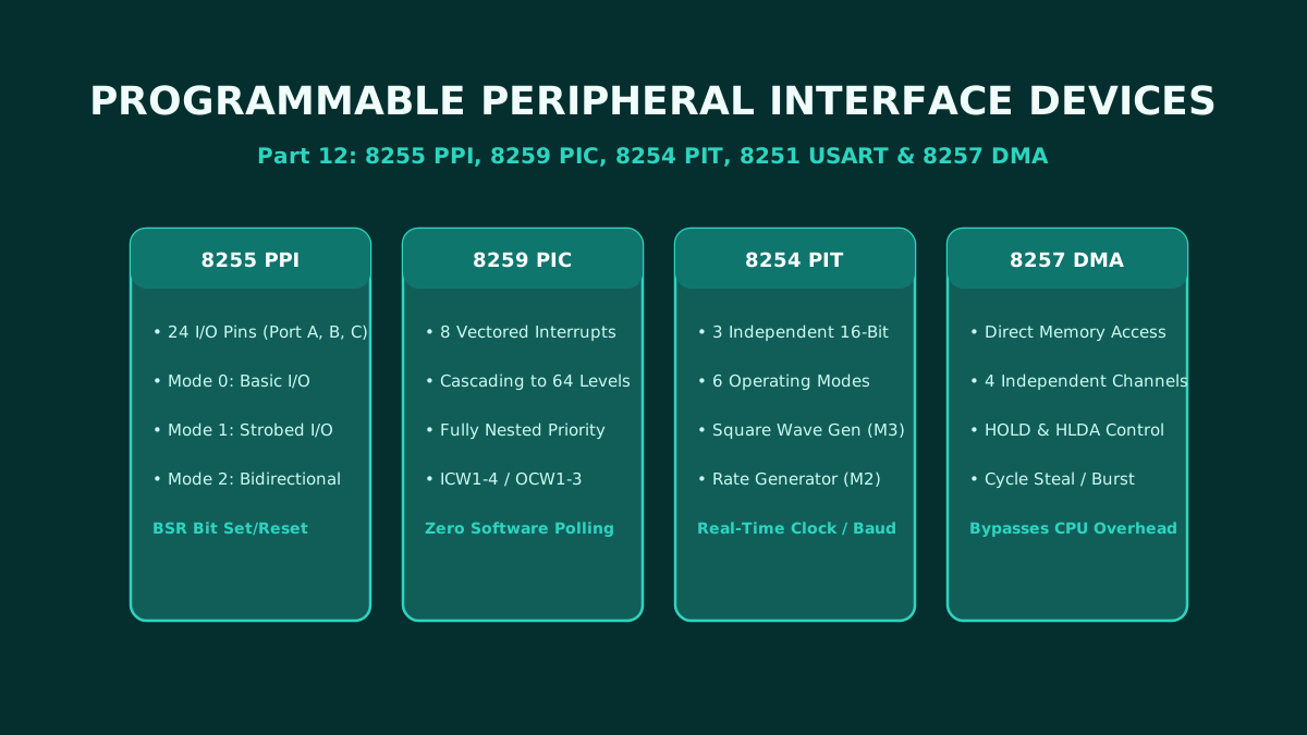
Part 12: Programmable Peripheral Interface ICs: Architecture and Pin Configuration of 8255, 8259, 8254, 8251, and 8257
The ultimate hardware reference for microprocessor peripheral interface adapters: complete architecture, pin configurations, and control word programming for the 8255 PPI, 8259 PIC, 8254 PIT, 8251 USART, and 8257 DMA controller.
By Md. Harun-Or-Roshid
Part 11: Intel 8051 Microcontroller Architecture: Harvard Memory Map, SFRs, and I/O Port Circuits
A master-level architectural analysis of the Intel 8051 microcontroller: Microprocessor vs Microcontroller paradigm, Harvard memory organization, 128-byte internal RAM layout, SFR registers, and internal circuits of Ports 0–3.
By Md. Harun-Or-Roshid
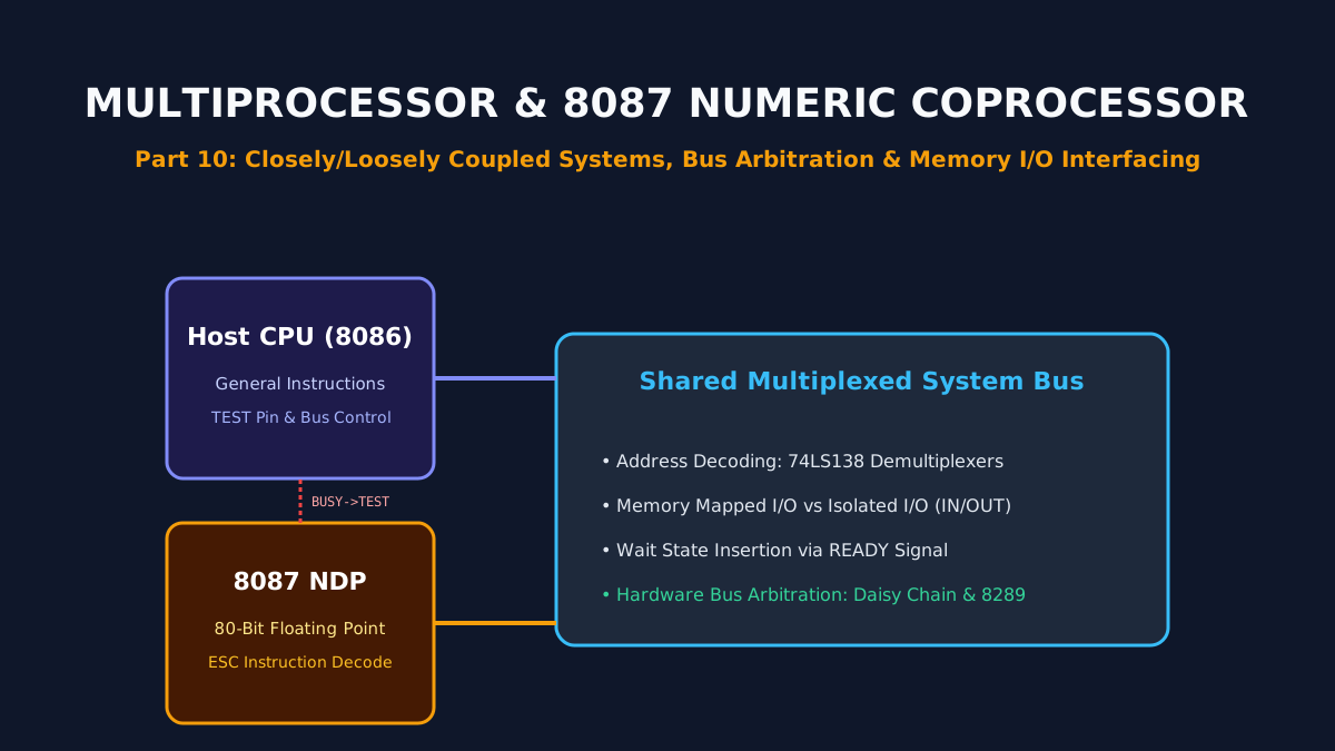
Part 10: Multiprocessor Configurations, 8087 Numeric Coprocessor, and Memory/IO Interfacing
Architectural principles of multiprocessor systems: closely vs loosely coupled topologies, hardware bus arbitration, the Intel 8087 floating-point NDP, and memory-mapped vs isolated I/O interfacing.
By Md. Harun-Or-Roshid
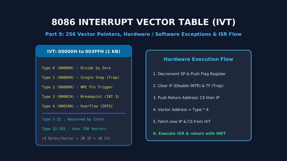
Part 9: Interrupt Structures and Vector Pointer Table in Intel 8086: Hardware, Software, and Exception Handling
A deep dive into 8086 interrupt processing: the 1 KB Interrupt Vector Table (IVT), dedicated Type 0–4 exceptions, hardware NMI/INTR lines, the 6-step interrupt response cycle, and the IRET sequence.
By Md. Harun-Or-Roshid