Part 9: Interrupt Structures and Vector Pointer Table in Intel 8086: Hardware, Software, and Exception Handling
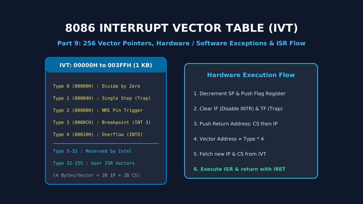
Asynchronous Exception & Hardware Event Handling
In embedded computing and general operating systems, unexpected asynchronous events (such as peripheral data arrival, power supply decay, or mathematical division errors) require the CPU to halt its sequential execution, preserve its current program state, service the event, and resume execution without data corruption. In Part 9, we dissect the 8086 Interrupt Vector Table (IVT), analyze the five dedicated hardware exceptions (Type 0 through Type 4), and trace the exact 6-step hardware execution sequence triggered upon interrupt receipt.
1. The 8086 Interrupt Vector Table (IVT)
The Intel 8086 supports up to 256 unique interrupt types, numbered from Type 0 to Type 255. The entry addresses (Interrupt Service Routine - ISR pointers) for all 256 interrupts are organized into a dedicated memory table known as the Interrupt Vector Table (IVT), physically mapped into the lowest 1 KB of system RAM from 00000H to 003FFH.
Vector Pointer Structure & Address Calculation
Each vector entry in the table requires exactly 4 bytes of memory:
- Lower 2 Bytes: The 16-bit offset address of the ISR, loaded into the Instruction Pointer (
IP). - Upper 2 Bytes: The 16-bit base address of the ISR segment, loaded into the Code Segment Register (
CS).
The starting memory address in the IVT for any given interrupt Type $N$ is calculated by:
INT 21H (MS-DOS API, $N = 33_{10}$ or $21\text{H}$):$\text{Address} = 21\text{H} \times 4 = 84\text{H}$ ($00084\text{H}$).
- Bytes at
00084H-00085H contain the new IP.- Bytes at
00086H-00087H contain the new CS.
2. Dedicated & Predefined Interrupts (Types 0 to 4)
| Interrupt Type | IVT Address | Trigger Source | Operational Behavior & Purpose |
|---|---|---|---|
| Type 0 (Divide Error) | 00000H - 00003H | Internal Hardware Exception | Automatically generated when a DIV or IDIV instruction attempts division by zero, or when the calculated quotient is too large to fit in the destination register (AX or AL). |
| Type 1 (Single Step / Trap) | 00004H - 00007H | Trap Flag (TF) = 1 | If TF is set, the CPU generates an internal Type 1 interrupt after executing each individual instruction. Enables interactive software debuggers (e.g. GDB) to inspect CPU registers between single instructions. |
| Type 2 (NMI) | 00008H - 0000BH | External NMI Pin (Pin 17) | Non-Maskable Interrupt: Positive edge-triggered. Cannot be disabled by the Interrupt Enable Flag (IF). Reserved for catastrophic hardware failures (RAM parity errors, bus faults, impending AC power drop). |
| Type 3 (Breakpoint) | 0000CH - 0000FH | INT 3 Opcode (0CCH) | A special 1-byte software instruction that software debuggers patch into memory over an instruction opcode to pause program execution at designated breakpoints. |
| Type 4 (Overflow) | 00010H - 00013H | INTO Opcode (if OF = 1) | Interrupt On Overflow: If the Overflow Flag (OF) is set to 1 following a signed arithmetic operation, the INTO instruction generates a Type 4 interrupt to trigger an overflow recovery routine. |
3. The 6-Step Hardware Interrupt Execution Cycle
Whenever an active interrupt request occurs (and is enabled), the 8086 hardware executes the following microcode sequence before executing the first line of the ISR:
Stack the Flag Register:
SP <- SP - 2; Memory[SS:SP] <- 16-bit Flag Register
Disable Nested Interrupts & Traps:
IF <- 0 (Disable maskable INTR interrupts); TF <- 0 (Disable single-step mode)
Stack the Return Code Segment (CS):
SP <- SP - 2; Memory[SS:SP] <- CS
Stack the Return Instruction Pointer (IP):
SP <- SP - 2; Memory[SS:SP] <- IP
Fetch New ISR Address from IVT:
IP <- Memory[Type * 4]; CS <- Memory[Type * 4 + 2]
Flush Pipeline & Execute ISR:
Clear BIU prefetch queue; fetch instructions starting from new CS:IP.
4. Returning with the IRET Instruction
Every Interrupt Service Routine must conclude with the IRET (Interrupt Return) instruction rather than a standard RET. The IRET instruction pops the top six bytes from the stack in reverse order:
Restoring the Flag register restores the original condition codes (Carry, Zero, Sign) and the original state of the Interrupt Flag (IF), seamlessly resuming the interrupted program without leaving any residual side effects.
Summary & Next Step
In Part 10, we explore Multiprocessor Configurations and Memory/IO Interfacing: closely vs loosely coupled multiprocessing, bus arbitration schemes, the Intel 8087 numeric math coprocessor, and address decoding using 74LS138 decoders.
Related reading
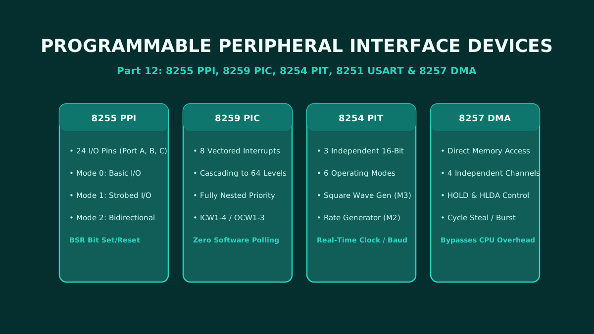
Part 12: Programmable Peripheral Interface ICs: Architecture and Pin Configuration of 8255, 8259, 8254, 8251, and 8257
The ultimate hardware reference for microprocessor peripheral interface adapters: complete architecture, pin configurations, and control word programming for the 8255 PPI, 8259 PIC, 8254 PIT, 8251 USART, and 8257 DMA controller.
By Md. Harun-Or-Roshid
Part 11: Intel 8051 Microcontroller Architecture: Harvard Memory Map, SFRs, and I/O Port Circuits
A master-level architectural analysis of the Intel 8051 microcontroller: Microprocessor vs Microcontroller paradigm, Harvard memory organization, 128-byte internal RAM layout, SFR registers, and internal circuits of Ports 0–3.
By Md. Harun-Or-Roshid
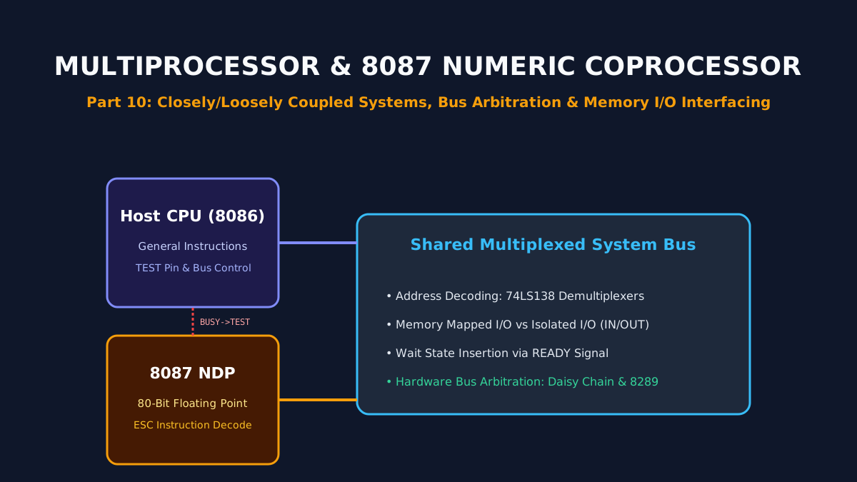
Part 10: Multiprocessor Configurations, 8087 Numeric Coprocessor, and Memory/IO Interfacing
Architectural principles of multiprocessor systems: closely vs loosely coupled topologies, hardware bus arbitration, the Intel 8087 floating-point NDP, and memory-mapped vs isolated I/O interfacing.
By Md. Harun-Or-Roshid
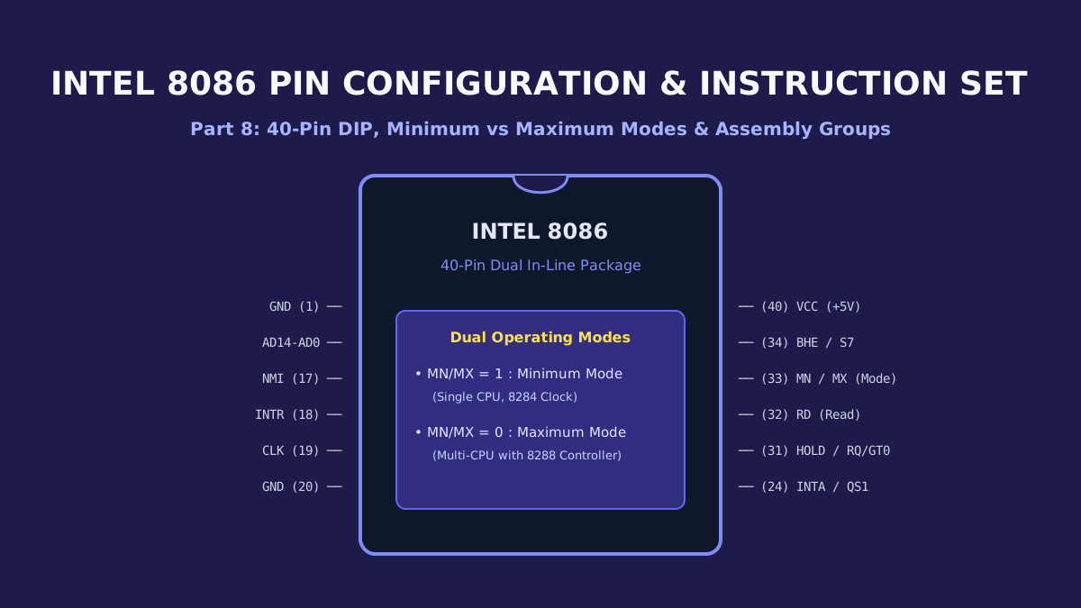
Part 8: Intel 8086 Pin Configuration, Operating Modes (Min/Max), and Comprehensive Instruction Set
Exhaustive hardware guide to the 40-pin Intel 8086: multiplexed address/data pins, Minimum Mode uniprocessor vs Maximum Mode multiprocessor circuits with the 8288 bus controller, and complete instruction set categorization.
By Md. Harun-Or-Roshid