Part 4: Intel 8085 Instruction Set and Addressing Modes: Data Formats, Opcodes, and Machine Cycles
Instruction Set Architecture (ISA) Mastery
A computer microprocessor interprets binary machine code commands through its instruction set. The Intel 8085 supports 74 basic instructions that expand into 246 distinct opcode variations. In Part 4, we examine how 8085 instructions are formatted in memory, study the five fundamental addressing modes that dictate operand retrieval, classify instructions into functional engineering groups, and dissect the clock states (T-states) that form machine cycles.
1. Anatomy of an Instruction: Opcode & Operand
Every assembly language instruction consists of two indispensable components:
- Opcode (Operation Code): The binary bit pattern that identifies the specific task to be executed by the CPU (e.g., copy data, add numbers, compare, branch). In the 8085, all opcodes are 8 bits (1 byte) wide.
- Operand: The data on which the operation is performed. An operand may be an 8-bit immediate number, an internal register (A, B, C, D, E, H, L), a 16-bit memory address, or an 8-bit I/O port address.
2. The Three 8085 Instruction Formats
Based on memory word requirements, 8085 instructions are categorized into three physical formats:
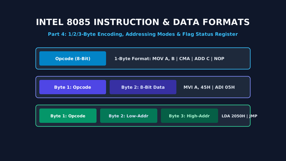
1-Byte Instructions
8 Bits TotalBoth the opcode and operand specification are encoded entirely within a single 8-bit memory byte. No additional data or address bytes follow.
| Mnemonic | Hex Opcode | Binary Encoding | Functional Description |
|---|---|---|---|
| MOV A, B | 78H | 01 111 000 | Copy content of Register B into Accumulator A |
| ADD C | 81H | 10 000 001 | Add Register C to Accumulator, update flags |
| CMA | 2FH | 00 101 111 | Complement Accumulator (1's complement) |
| HLT | 76H | 01 110 110 | Halt CPU execution and enter bus pause state |
2-Byte Instructions
16 Bits TotalByte 1 specifies the 8-bit opcode. Byte 2 supplies an 8-bit immediate data constant or 8-bit I/O device port address.
| Mnemonic | Byte 1 (Opcode) | Byte 2 (Operand) | Functional Description |
|---|---|---|---|
| MVI A, 45H | 3EH | 45H | Move immediate 8-bit byte 45H into Accumulator |
| ADI 0AH | C6H | 0AH | Add immediate data 0AH to Accumulator |
| IN 80H | DBH | 80H | Read byte from peripheral I/O port address 80H into A |
3-Byte Instructions
24 Bits TotalByte 1 specifies the 8-bit opcode. Byte 2 contains the low-order 8 bits of a 16-bit memory address. Byte 3 contains the high-order 8 bits of the memory address (Little-Endian storage).
| Mnemonic | Byte 1 | Byte 2 (Low Address) | Byte 3 (High Address) | Functional Description |
|---|---|---|---|---|
| LDA 2050H | 3AH | 50H | 20H | Load Accumulator directly with memory content at 2050H |
| STA 3000H | 32H | 00H | 30H | Store Accumulator content directly into memory at 3000H |
| LXI H, 4000H | 21H | 00H | 40H | Load 16-bit immediate address 4000H into HL register pair |
| JMP 2000H | C3H | 00H | 20H | Unconditional jump: load 2000H directly into Program Counter |
3. The Five Addressing Modes of 8085
Addressing modes describe the method by which an instruction references its operands. The 8085 implements five distinct modes:
1. Immediate Addressing Mode
The operand data is embedded directly within the instruction bytes following the opcode. Identified by mnemonics ending in 'I' (Immediate).
Example: MVI A, 25H (Loads constant 25H into Accumulator); LXI B, 1050H.
2. Register Addressing Mode
The operands are stored in CPU internal general-purpose registers (A, B, C, D, E, H, L). No memory bus read/write cycles are required to fetch operands, yielding single-byte, fast execution.
Example: MOV B, C (Copies register C into B); ADD D (Adds register D to A).
3. Direct Addressing Mode
The 16-bit memory address where the operand resides is explicitly provided within bytes 2 and 3 of the instruction.
Example: LDA 2500H (Reads byte from memory 2500H into A); STA 2500H.
4. Register Indirect Addressing Mode
The instruction specifies a 16-bit register pair (typically HL, denoted as 'M') that holds the memory address of the operand.
Example: MOV A, M (Fetches data from memory address held in HL register pair into A); STAX B.
5. Implied / Implicit Addressing Mode
The operand is implicit in the definition of the opcode itself; no explicit register or address is specified.
Example: CMA (Inverts accumulator bits); RAL (Rotate Accumulator Left through Carry); EI (Enable Interrupts).
4. Machine Cycles & T-States Overview
Every machine cycle is composed of a specific number of discrete clock periods called T-states:
- Opcode Fetch Machine Cycle ($M_1$): Requires 4 T-states ($T_1 - T_4$) for standard instructions, or 6 T-states for instructions requiring internal decode overhead (such as
DCXor conditional jumps). In $T_1$, address is placed on bus; in $T_2$, memory read strobe is asserted; in $T_3$, opcode byte is read into IR; in $T_4$, opcode is decoded. - Memory Read ($M_R$) & Memory Write ($M_W$): Each requires 3 T-states ($T_1 - T_3$).
- I/O Read ($M_{IOR}$) & I/O Write ($M_{IOW}$): Each requires 3 T-states ($T_1 - T_3$).
Summary & Next Step
Equipped with a complete understanding of instructions, addressing modes, and machine cycles, we transition in Part 5 into Assembly Language Programming in 8085, implementing arithmetic routines, array sorting (bubble sort), code conversions, and calibrated delay loops.
Related reading
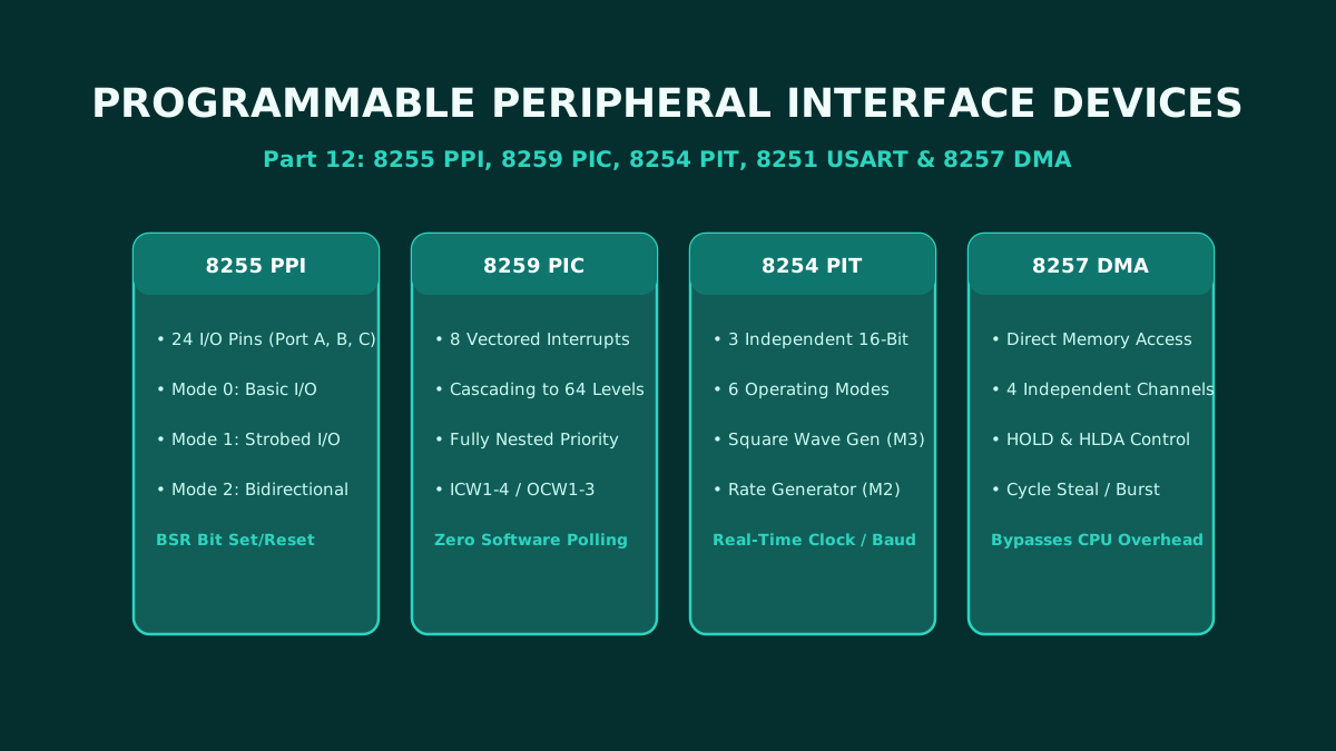
Part 12: Programmable Peripheral Interface ICs: Architecture and Pin Configuration of 8255, 8259, 8254, 8251, and 8257
The ultimate hardware reference for microprocessor peripheral interface adapters: complete architecture, pin configurations, and control word programming for the 8255 PPI, 8259 PIC, 8254 PIT, 8251 USART, and 8257 DMA controller.
By Md. Harun-Or-Roshid
Part 11: Intel 8051 Microcontroller Architecture: Harvard Memory Map, SFRs, and I/O Port Circuits
A master-level architectural analysis of the Intel 8051 microcontroller: Microprocessor vs Microcontroller paradigm, Harvard memory organization, 128-byte internal RAM layout, SFR registers, and internal circuits of Ports 0–3.
By Md. Harun-Or-Roshid
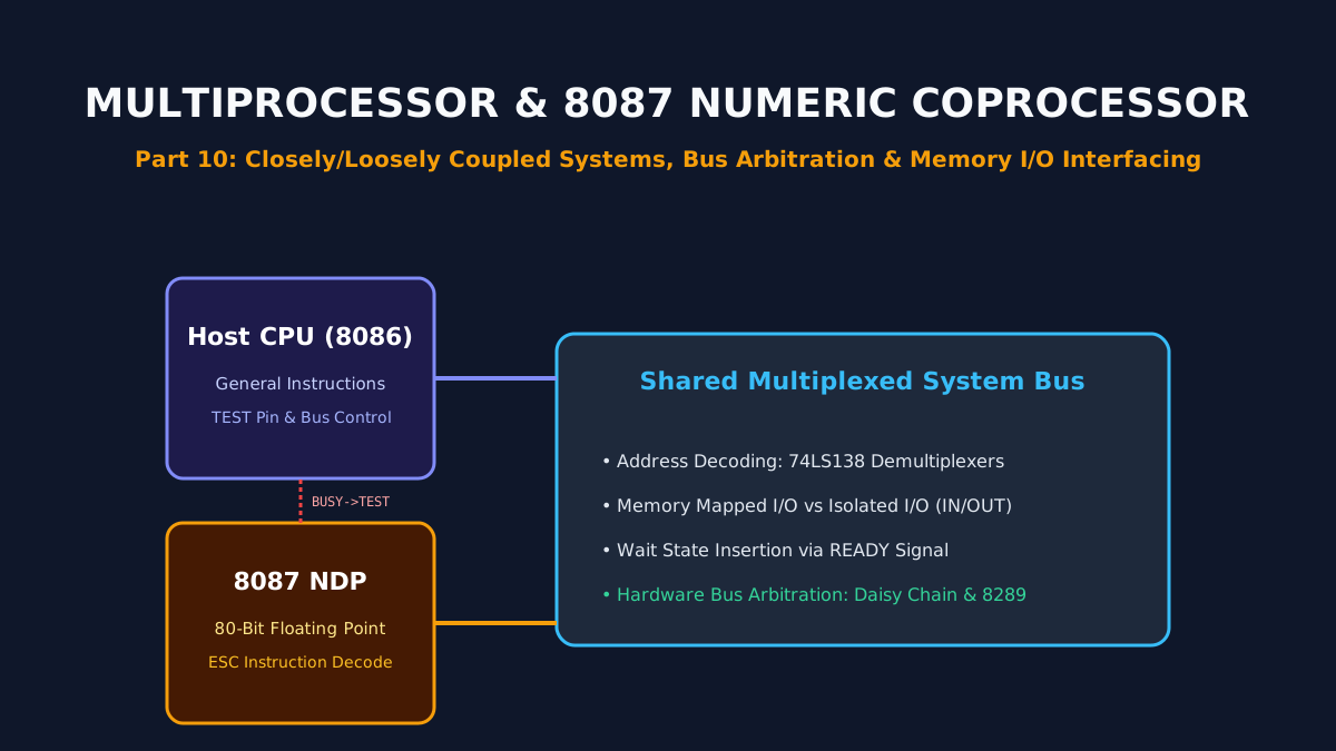
Part 10: Multiprocessor Configurations, 8087 Numeric Coprocessor, and Memory/IO Interfacing
Architectural principles of multiprocessor systems: closely vs loosely coupled topologies, hardware bus arbitration, the Intel 8087 floating-point NDP, and memory-mapped vs isolated I/O interfacing.
By Md. Harun-Or-Roshid
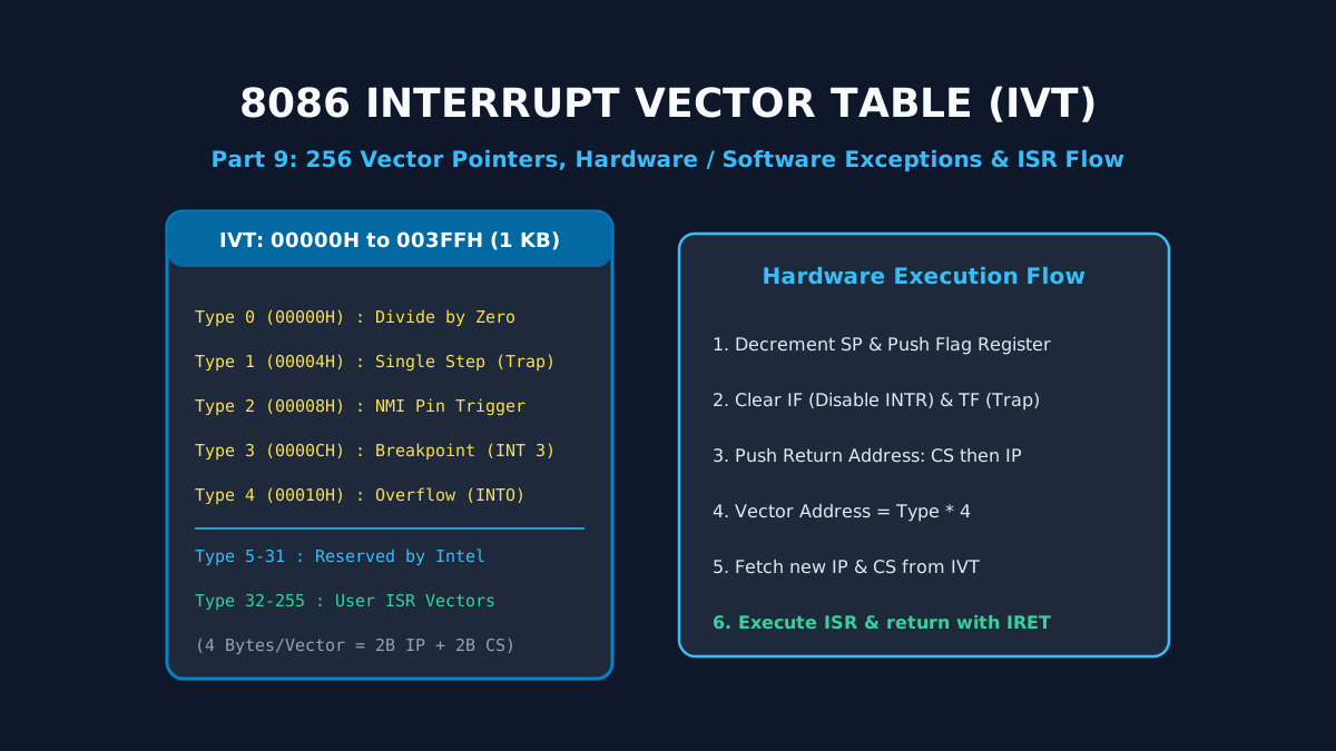
Part 9: Interrupt Structures and Vector Pointer Table in Intel 8086: Hardware, Software, and Exception Handling
A deep dive into 8086 interrupt processing: the 1 KB Interrupt Vector Table (IVT), dedicated Type 0–4 exceptions, hardware NMI/INTR lines, the 6-step interrupt response cycle, and the IRET sequence.
By Md. Harun-Or-Roshid