Data Flow Diagram
What is DFD?
- A data flow diagram (DFD) is a graphical representation of the “flow” of data through an information system, modelling its process aspects.
- A DFD is often used as a preliminary step to create an overview of the system, which can later be elaborated.
- Show users how data moves between different processes in a system.


• Two common systems of symbols are named after their creators:
• Yourdon and Coad
• Yourdon and DeMarco
• Gane and Sarson
• One main difference in their symbols is that Yourdon-Coad and Yourdon-DeMarco use circles for processes, while Gane and Sarson use rectangles with rounded corners, sometimes called lozenges.
• There are other symbol variations in use as well, so the important thing to keep in mind is to be clear and consistent in the shapes and notations you use to communicate and collaborate with others.
Using any convention’s DFD rules or guidelines, the symbols depict the four components of data flow diagrams.

• They are the sources and destinations of information entering or leaving the system.
• They might be an outside organization or person, a computer system or a business system.
• They are also known as terminators, sources and sinks or actors.
They are typically drawn on the edges of the diagram.

• It might perform computations, or sort data based on logic, or direct the data flow based on business rules.
• A short label is used to describe the process, such as “Submit payment.”

• Each data store receives a simple label, such as “Orders.”

• It portrays the interface between the other components and is shown with arrows, typically labeled with a short data name, like “Billing details.”

DFD rules and tips
- Each process should have at least one input and an output.
- Each data store should have at least one data flow in and one data flow out.
- Data stored in a system must go through a process.
- All processes in a DFD go to another process or a data store.
- Each process should have at least one input and an output.
- Each data store should have at least one data flow in and one data flow out.
- Data stored in a system must go through a process.
- All processes in a DFD go to another process or a data store.
DFD levels and layers: From context diagrams to pseudocode
- A data flow diagram can dive into progressively more detail by using levels and layers, zeroing in on a particular piece.
- DFD levels are numbered 0, 1 or 2, and occasionally go to even Level 3 or beyond.
- The necessary level of detail depends on the scope of what you are trying to accomplish.
DFD Level 0
- DFD Level 0 is also called a Context Diagram.
- It’s a basic overview of the whole system or process being analyzed or modeled.
- It’s designed to be an at-a-glance view, showing the system as a single high-level process, with its relationship to external entities.
- It should be easily understood by a wide audience, including stakeholders, business analysts, data analysts and developers.

DFD Level 1
- DFD Level 1 provides a more detailed breakout of pieces of the Context Level Diagram.
- You will highlight the main functions carried out by the system, as you break down the high-level process of the Context Diagram into its sub processes.

• DFD Level 2 then goes one step deeper into parts of Level 1.
• It may require more text to reach the necessary level of detail about the system’s functioning.

• Doing so can create complexity that makes it difficult to communicate, compare or model effectively.

Context Diagram For Level 0 Diagram
- Level 0 Diagram

Context Diagram For Level 1 Diagram
- Level 1 DFD for Process 2

Context Diagram For Level 2 Diagram
- Level 2 DFD for Process 2.2

Context Diagram For Level 1, 2, 0 Diagram

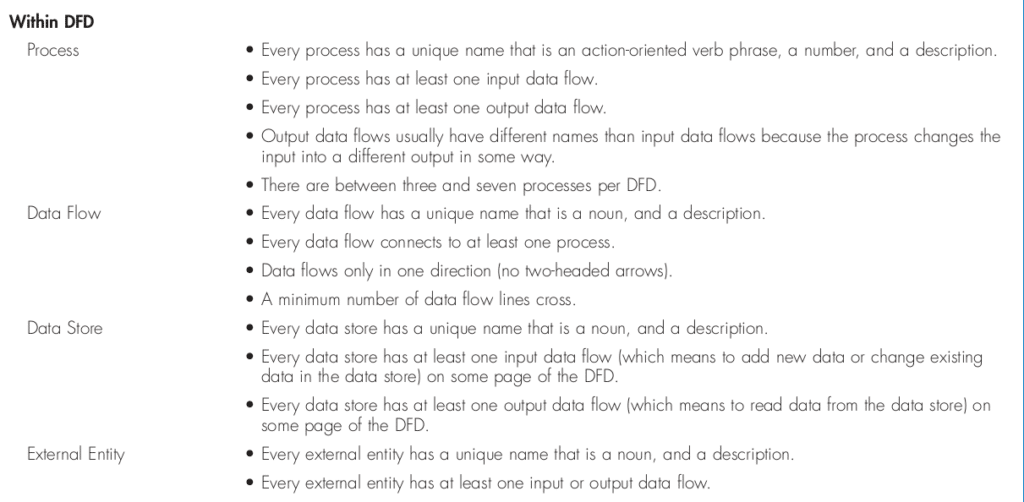
Process
• Every process has a unique name that is an action-oriented verb phrase, a number, and a description.
• Every process has at least one input data flow.
• Every process has at least one output data flow.
• Output data flows usually have different names than input data flows because the process changes the
input into a different output in some way.
• There are between three and seven processes per DFD
Data Flow
• Every data flow has a unique name that is a noun, and a description.
• Every data flow connects to at least one process.
• Data flows only in one direction (no two-headed arrows).
• A minimum number of data flow lines cross.
Data Store
• Every data store has a unique name that is a noun, and a description.
• Every data store has at least one input data flow (which means to add new data or change existing
data in the data store) on some page of the DFD.
• Every data store has at least one output data flow (which means to read data from the data store) on
some page of the DFD.
External Entity
• Every external entity has a unique name that is a noun, and a description.
• Every external entity has at least one input or output data flow.
Within DFD all the elements with features

Across DFDs :

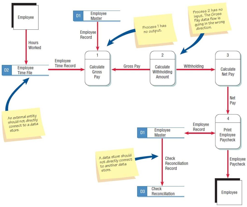
Errors in DFD:
- An entity cannot provide data to another entity without some processing occurred.
- Data cannot move directly from an entity to a data story without being processed.
- Data cannot move directly from a data store without being processed.
- Data cannot move directly from one data store to another without being processed.
Other frequently-made mistakes in DFD
A second class of DFD mistakes arise when the outputs from one processing step do not match its inputs and they can be classified as:
- Black holes: A processing step may have input flows but no output flows.
- Miracles: A processing step may have output flows but no input flows.
- Grey holes: A processing step may have outputs that are greater than the sum of its inputs


0 Comments