DC – Error Detection & Correction
There are many reasons such as noise, cross-talk etc., which may help data to get corrupted during transmission. The upper layers work on some generalized view of network architecture and are not aware of actual hardware data processing. Hence, the upper layers expect error-free transmission between the systems. Most of the applications would not function expectedly if they receive erroneous data. Applications such as voice and video may not be that affected and with some errors they may still function well.
Data-link layer uses some error control mechanism to ensure that frames (data bit streams) are transmitted with certain level of accuracy. But to understand how errors is controlled, it is essential to know what types of errors may occur.
Types of Errors
There may be three types of errors:
- Single bit error
In a frame, there is only one bit, anywhere though, which is corrupt.
- Multiple bits error
Frame is received with more than one bits in corrupted state.
- Burst error
Frame contains more than1 consecutive bits corrupted.

Error control mechanism may involve two possible ways:
- Error detection
- Error correction
Error Detection
Errors in the received frames are detected by means of Parity Check and Cyclic Redundancy Check (CRC). In both cases, few extra bits are sent along with actual data to confirm that bits received at other end are same as they were sent. If the counter-check at receiver’ end fails, the bits are considered corrupted.
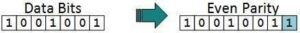
Parity Check
One extra bit is sent along with the original bits to make number of 1s either even in case of even parity, or odd in case of odd parity.
The sender while creating a frame counts the number of 1s in it. For example, if even parity is used and number of 1s is even then one bit with value 0 is added. This way number of 1s remains even.If the number of 1s is odd, to make it even a bit with value 1 is added.
The receiver simply counts the number of 1s in a frame. If the count of 1s is even and even parity is used, the frame is considered to be not-corrupted and is accepted. If the count of 1s is odd and odd parity is used, the frame is still not corrupted.
If a single bit flips in transit, the receiver can detect it by counting the number of 1s. But when more than one bits are erroneous, then it is very hard for the receiver to detect the error.
Cyclic Redundancy Check (CRC)
CRC is a different approach to detect if the received frame contains valid data. This technique involves binary division of the data bits being sent. The divisor is generated using polynomials. The sender performs a division operation on the bits being sent and calculates the remainder. Before sending the actual bits, the sender adds the remainder at the end of the actual bits. Actual data bits plus the remainder is called a codeword. The sender transmits data bits as codewords.
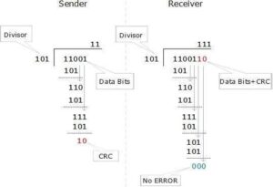
At the other end, the receiver performs division operation on codewords using the same CRC divisor. If the remainder contains all zeros the data bits are accepted, otherwise it is considered as there some data corruption occurred in transit.
Error Correction
In the digital world, error correction can be done in two ways:
- Backward Error Correction When the receiver detects an error in the data received, it requests back the sender to retransmit the data unit.
- Forward Error Correction When the receiver detects some error in the data received, it executes errorcorrecting code, which helps it to auto-recover and to correct some kinds of errors.
The first one, Backward Error Correction, is simple and can only be efficiently used where retransmitting is not expensive. For example, fiber optics. But in case of wireless transmission retransmitting may cost too much. In the latter case, Forward Error Correction is used.
To correct the error in data frame, the receiver must know exactly which bit in the frame is corrupted. To locate the bit in error, redundant bits are used as parity bits for error detection.For example, we take ASCII words (7 bits data), then there could be 8 kind of information we need: first seven bits to tell us which bit is error and one more bit to tell that there is no error.
For m data bits, r redundant bits are used. r bits can provide 2r combinations of information. In m+r bit codeword, there is possibility that the r bits themselves may get corrupted. So the number of r bits used must inform about m+r bit locations plus no-error information, i.e. m+r+1.
2r> = m+r+1
DC – Data-link Control & Protocols
Data-link layer is responsible for implementation of point-to-point flow and error control mechanism.
Flow Control
When a data frame (Layer-2 data) is sent from one host to another over a single medium, it is required that the sender and receiver should work at the same speed. That is, sender sends at a speed on which the receiver can process and accept the data. What if the speed (hardware/software) of the sender or receiver differs? If sender is sending too fast the receiver may be overloaded, (swamped) and data may be lost.
Two types of mechanisms can be deployed to control the flow:
- Stop and Wait
This flow control mechanism forces the sender after transmitting a data frame to stop and wait until the acknowledgement of the data-frame sent is received.
- Sliding Window
In this flow control mechanism, both sender and receiver agree on the number of data-frames after which the acknowledgement should be sent. As we learnt, stop and wait flow control mechanism wastes resources, this protocol tries to make use of underlying resources as much as possible.
Error Control
When data-frame is transmitted, there is a probability that data-frame may be lost in the transit or it is received corrupted. In both cases, the receiver does not receive the correct data-frame and sender does not know anything about any loss.In such case, both sender and receiver are equipped with some protocols which helps them to detect transit errors such as loss of data-frame. Hence, either the sender retransmits the data-frame or the receiver may request to resend the previous data-frame.
Requirements for error control mechanism:
- Error detection – The sender and receiver, either both or any, must ascertain that there is some error in the transit.
- Positive ACK – When the receiver receives a correct frame, it should acknowledge it.
- Negative ACK – When the receiver receives a damaged frame or a duplicate frame, it sends a NACK back to the sender and the sender must retransmit the correct frame.
- Retransmission: The sender maintains a clock and sets a timeout period. If an acknowledgement of a dataframe previously transmitted does not arrive before the timeout the sender retransmits the frame, thinking that the frame or it’s acknowledgement is lost in transit.
There are three types of techniques available which Data-link layer may deploy to control the errors by Automatic Repeat Requests (ARQ):
-
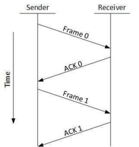
Stop-and-wait ARQ
The following transition may occur in Stop-and-Wait ARQ:
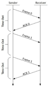
- The sender maintains a timeout counter.
- When a frame is sent, the sender starts the timeout counter. o If acknowledgement of frame comes in time, the sender transmits the next frame in queue. o If acknowledgement does not come in time, the sender assumes that either the frame or its acknowledgement is lost in transit. Sender retransmits the frame and starts the timeout counter.
- If a negative acknowledgement is received, the sender retransmits the frame.
-
Go-Back-N ARQ
Stop and wait ARQ mechanism does not utilize the resources at their best.When the acknowledgement is received, the sender sits idle and does nothing. In Go-Back-N ARQ method, both sender and receiver maintain a window.
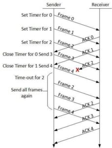
The sending-window size enables the sender to send multiple frames without receiving the acknowledgement of the previous ones. The receiving-window enables the receiver to receive multiple frames and acknowledge them. The receiver keeps track of incoming frame’s sequence number.
When the sender sends all the frames in window, it checks up to what sequence number it has received positive acknowledgement. If all frames are positively acknowledged, the sender sends next set of frames. If sender finds that it has received NACK or has not receive any ACK for a particular frame, it retransmits all the frames after which it does not receive any positive ACK.
-
Selective Repeat ARQ
In Go-back-N ARQ, it is assumed that the receiver does not have any buffer space for its window size and has to process each frame as it comes. This enforces the sender to retransmit all the frames which are not acknowledged.
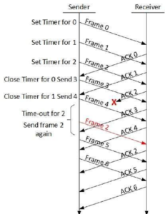
In Selective-Repeat ARQ, the receiver while keeping track of sequence numbers, buffers the frames in memory and sends NACK for only frame which is missing or damaged.
The sender in this case, sends only packet for which NACK is received.
DC – Network Layer Introduction
Layer-3 in the OSI model is called Network layer. Network layer manages options pertaining to host and network addressing, managing sub-networks, and internetworking.
Network layer takes the responsibility for routing packets from source to destination within or outside a subnet. Two different subnet may have different addressing schemes or non-compatible addressing types. Same with protocols, two different subnet may be operating on different protocols which are not compatible with each other. Network layer has the responsibility to route the packets from source to destination, mapping different addressing schemes and protocols.
Layer-3 Functionalities
Devices which work on Network Layer mainly focus on routing. Routing may include various tasks aimed to achieve a single goal. These can be:
- Addressing devices and networks.
- Populating routing tables or static routes.
- Queuing incoming and outgoing data and then forwarding them according to quality of service constraints set for those packets.
- Internetworking between two different subnets.
- Delivering packets to destination with best efforts.
- Provides connection oriented and connection less mechanism.
Network Layer Features
With its standard functionalities, Layer 3 can provide various features as:
- Quality of service management
- Load balancing and link management
- Security
- Interrelation of different protocols and subnets with different schema.
- Different logical network design over the physical network design.
- L3 VPN and tunnels can be used to provide end to end dedicated connectivity.
Internet protocol is widely respected and deployed Network Layer protocol which helps to communicate end to end devices over the internet. It comes in two flavors. IPv4 which has ruled the world for decades but now is running out of address space. IPv6 is created to replace IPv4 and hopefully mitigates limitations of IPv4 too.
0 Comments