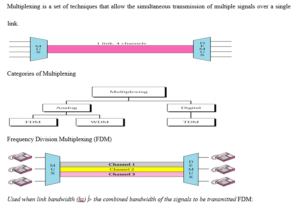
Signal multiplexing is a process in which multiple signals can be transmitted together over the same communication medium simultaneously.
Time division multiplexing
- Time division multiplexing is a technique of separating the signals in time domain.
- In TDM the transmission from multiple sources take place on the same medium but not at the same time.
- The transmissions from various sources are interleaved in time domain. In other words, the data from the various sources is arranged in non contiguous manner by dividing the data into small chunks, which also makes the system efficient.
- Pulse code modulation is the most common encoding technique used for TDM digital signals.
- PCM system used in North America is a 24-channel system with the sampling rate of 8000 samples per second, 8 bits per sample and a pulse width of 0.625 μs.
- We can calculate that sampling interval is 1/8000 = 125 μs, and period required for each pulse group is 8 x 0.625 = 5 μs.
- If we transmit only one channel without using the multiplexing technique, then the transmission will contain 8000 frames per second, which will consist of the activity only during the first 5 μs and nothing at all during the rest 120 μs.
- Thus will be wasteful and employs complicated method for encoding single channel. Therefore TDM technique is used so that each 125 μs frame is used to provide 24 adjacent channel time slots with the twenty-fifth time slot for synchronization.
- Fig1 shows the time division multiplexing of the data from the various channels of the PCM system. TDM finds application in the transmission of SDH and SONET system, GSM telephone system etc.
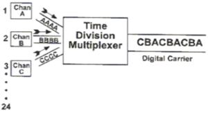
Fig.1 TDM
Frequency division multiplexing
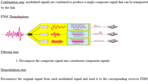
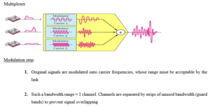
- Frequency division multiplexing is a technique of separating the signals in frequency domain. In other words, many narrow bandwidth channels are combined and transmitted over a single wide bandwidth transmission system without interfering with each other. Thus FDM takes up a given bandwidth and subdivide it into narrower segments with each segment carrying different information.
- FDM is an analog multiplexing scheme where the information entering the FDM system must be analog and it remains analog throughout the transmission.
- If the original source information is digital then it must first be converted into equivalent analog signal and then multiplexed in frequency domain.
- A common example of FDM is the commercial AM broadcast band. 535 kHz to 1605 kHz is the frequency spectrum occupied by the AM band.
- Information signal at each broadcast station occupies a bandwidth between 0 Hz and 5 Hz. If we transmit information from each station with the original spectrum, then it would be difficult to differentiate one station’s transmissions from another. Thus to avoid this situation, each station amplitude modulates a different carrier frequency to produce a 10 kHz signal.
- Since the carrier frequencies of adjacent stations are separated by 10 kHz signal, the total commercial AM broadcast band is divided into 107 slots with 10 kHz frequency, which are arranged next to each other in the frequency domain.
- The receiver tunes in to a particular frequency band associated with the station’s transmission in order to receive that particular station.
- The Fig2 shows FDM technique applied to the commercial AM broadcast station for transmission on a common medium.
- FDM technique finds application in commercial FM and television broadcasting, telephone and communication systems etc.
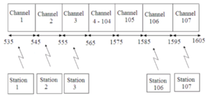
Fig.2 FDM
FDM in Telephone Networks
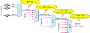
- To maximize efficiency, telephone companies have traditionally multiplexed signals from lowerbandwidth lines onto higher-bandwidth lines.
- Many switched or leased lines can be combined into fewer but bigger channels
- For analog lines, FDM is used
AT&T Analog Hierarchy
Time-Division Multiplexing

TDM is a digital multiplexing technique to combine data.
TDM: Time Slots and Frames
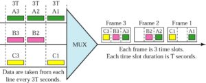
In a TDM, the data rate of the link is n times faster, and the unit duration is n times shorter.
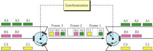
TDM: Interleaving
Mux: each connection in turn puts a data input into the path
Demux: each connection in turn receives a data unit from the path
TDM: Example 2
4 channels are multiplexed using TDM. If each channel sends 100 bytes/s and we multiplex 1 byte per channel, show the frame traveling on the link, the size of the frame, the duration of a frame, the frame rate, and the bit rate for the link.

TDM: Framing Bits
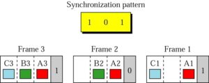
- Mux and Demux may be out of sync => bits are delivered to wrong receivers
- Need to separate between frames => extra bits are inserted into the head of each frame. A bit pattern must be followed so that time slots are separated accurately.
T1 Line for Analog Transmission
Analog signal => sampled => TDM

E Lines: Used in Europe
| E Line | Rate | Voice |
| (Mbps) | Channels | |
| E-1 | 2.048 | 30 |
| E-2 | 8.448 | 120 |
| E-3 | 34.368 | 480 |
| E-4 | 139.26 | 1920 |
Multiplexing and Inverse Multiplexing

Input: a data stream
Output: a number of sub-streams each sent over a low-speed line

0 Comments