Companding
In telecommunication and signal processing companding (occasionally called compansion) is a method of mitigating the detrimental effects of a channel with limited dynamic range. The name is a portmanteau of the words compressing and expanding. The use of companding allows signals with a large dynamic range to be transmitted over facilities that have a smaller dynamic range capability. Companding is employed in telephony and other audio applications such as professional wireless microphones and analog recording.
Model of Companding
The figure below represents the companding model in order to achieve non-uniform companding:
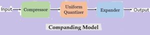
As we can see that the companding model consists of a compressor, a uniform quantizer and an expander.
We have already discussed that companding is formed by merging the compression and expanding. Initially at the transmitting end the signal is compressed and further at the receiving end the compressed signal is expanded in order to have the original signal.
Initially at the transmitting end, the signal is first provided to the compressor. The compressor unit amplifies the low value or weak signal in order to increase the signal level of the applied input signal.
While if the input signal is a high level signal or strong signal then compressor attenuates that signal before providing it to the uniform quantizer present in the model.
This is done in order to have an appropriate signal level as the input to the uniform quantizer. We know a high amplitude signal needs more bandwidth and also is more likely to distort. Similarly, some drawbacks are associated with low amplitude signal and thus there exist need for such a unit.
The operation performed by this block is known as compression thus the unit is called compressor.
The output of the compressor is provided to uniform quantizer where the quantization of the applied signal is performed.
At the receiver end, the output of the uniform quantizer is fed to the expander.
It performs the reverse of the process executed by the compressor. This unit when receives a low value signal then it attenuates it. While if a strong signal is achieved then the expander amplifies it.
This is done in order to achieve the originally transmitted signal at the output.
Characteristic of Compander
As we know companding is composed of compression and expanding. So, here in this session we will separately discuss the compressor and expander characteristic.
Compressor characteristic: The figure below shows the graphical representation of characteristic of the compressor:
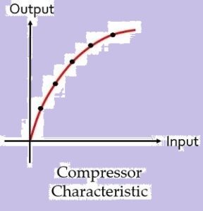
The graph clearly represents that the compressor provides high gain to weak signal and low gain to high input signal.
Expander characteristic: Here the figure shows the characteristic of expander:
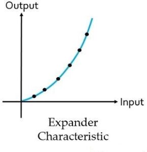
As we have already discussed that expander performs reverse operation of the compander. So, it is clear from the above figure that artificially boosted signals is attenuated to have the originally transmitted signal.
What is an equalizer?
An equalizer allows the sound in specified frequency bands to be amplified or reduced, in order to adjust the quality and character of the sound. There are different types of equalizer for various uses, such as the parametric equalizers that are controlled using the knobs built into each mixer channel, or the graphic equalizers that allow multiple frequency bands (such as 7, 15, or 31 bands) to be adjusted using sliders.
In general, the most commonly used equalizers are the parametric equalizers equipped on each channel of the mixer. Rarely are the sounds of microphones and instruments that are input to the mixer perfect for delivery as-is to the venue. When mixing music that involves many instruments, some parts may inevitably be difficult to pick out. In this situation, adjusting only volume and panning is not sufficient, and equalizers can be used to adjust each frequency band to make the best characteristics of each instrument stand out.
Pulse Position Modulation (PPM)
Definition: A modulation technique that allows variation in the position of the pulses according to the amplitude of the sampled modulating signal is known as Pulse Position Modulation (PPM). It is another type of PTM, where the amplitude and width of the pulses are kept constant and only the position of the pulses is varied.
Simply put, the pulse displacement is directly proportional to the sampled value of the message signal.
Basics of Pulse Position Modulation
- The information is transmitted with the varying position of the pulses in pulse position modulation.
- The basic idea about the generation of a PPM waveform is that here, as the amplitude of the message signal increases, the pulse shifts according to the reference.
Now, the question arises how the position of the pulses show variation?
A PPM signal is generated in reference to a PWM signal. Thus, the trailing edge of the PWM signal acts as the beginning point of the pulses of PPM signal.
Block diagram for generation of PPM signal
The figure below shows the block diagram for generating a PPM signal:
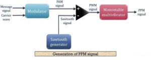
- Here, first, a PAM signal is produced with is further processed at the comparator in order to generate a PWM signal.
- The output of the comparator is fed to a monostable multi vibrator. It is negative edge triggered. Hence, with the trailing edge of the PWM signal, the output of the monostable goes high.
- This is why a pulse of PPM signal begins with the trailing edge of the PWM signal.
- It is to be noted in case of PPM that the duration for which the output will be high depends on the RC components of the multi vibrator. This is the reason why a constant width pulse is obtained in case of the PPM signal.
- With the modulating signal, the trailing edge of PWM signal shifts, thus with that shift, the PPM pulses shows shifts in its position.
The figure below shows the waveform representation of the PPM signal:
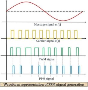
- Here, the first image shows the modulating signal, and the second one shows a carrier signal. The next one shows a PWM signal which is considered as reference for the generation of PPM signal shown in the last image.
- As we can see in the above figure that the point of ending the PWM pulse and the beginning of PPM pulse is coinciding, which can be clearly seen from the dotted line.
Detection (Demodulation) of PPM signal
The figure below shows the block diagram for the detection of a PPM signal at the receiver:
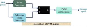
- The above figure that the demodulation circuit consists of a pulse generator, SR flip-flop, reference pulse generator and a PWM demodulator.
- The PPM signal transmitted from the modulation circuit gets distorted by the noise during transmission. This distorted PPM signal reaches the demodulator circuit. The pulse generator employed in the circuit generates a pulsed waveform. This waveform is of fixed duration which is fed to the reset pin (R) of the SR flip-flop.
- The reference pulse generator generates, reference pulse of a fixed period when transmitted PPM signal is applied to it. This reference pulse is used to set the flip-flop.
- These set and reset signals generate a PWM signal at the output of the flip-flop. This PWM signal is then further processed in order to provide the original message signal.
Advantages of Pulse Position Modulation
- Similar to PWM, PPM also shows better noise immunity as compared to PAM. This is so because information content is present in the position of the pulses rather than amplitude.
- As the amplitude and width of the pulses remain constant. Thus the transmission power also remains constant and does not show variation.
- Recovering a PPM signal from distorted PPM is quite easy.
- Interference due to noise in more minimal than PAM and PWM.
Disadvantages of Pulse Position Modulation
- In order to have proper detection of the signal at the receiver, transmitter and receiver must be in synchronization.
- The bandwidth requirement is large.
Applications of Pulse Position Modulation
The technique is used in an optical communication system, in radio control and in military applications.
0 Comments