Analog to Analog Modulation
Analog-to-analog conversion, or modulation, is the representation of analog information by an analog signal. It is a process by virtue of which a characteristic of carrier wave is varied according to the instantaneous amplitude of the modulating signal. This modulation is generally needed when a bandpass channel is required. Bandpass is a range of frequencies which are transmitted through a bandpass filter which is a filter allowing specific frequencies to pass preventing signals at unwanted frequencies. Representation of analog information by an analog signal
Why do we need it? Analog is already analog!!!
-
-
- Because we may have to use a band-pass channel
- Think about radio…
Analog to Analog Schemes are:
-
- Amplitude modulation (AM)
- Frequency modulation (FM)
- Phase modulation (PM)
-
Amplitude Modulation: AM
The modulation in which the amplitude of the carrier wave is varied according to the instantaneous amplitude of the modulating signal keeping phase and frequency as constant.
s(t) = (1+nax(t))cos(2fct)
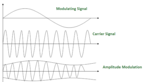
AM is normally implemented by using a simple multiplier because the amplitude of the carrier signal needs to be changed according to the amplitude of the modulating signal.
AM bandwidth:
The modulation creates a bandwidth that is twice the bandwidth of the modulating signal and covers a range centered on the carrier frequency.
Bandwidth= 2fm
Frequency Modulation: FM
The modulation in which the frequency of the carrier wave is varied according to the instantaneous amplitude of the modulating signal keeping phase and amplitude as constant. The figure below shows the concept of frequency modulation:
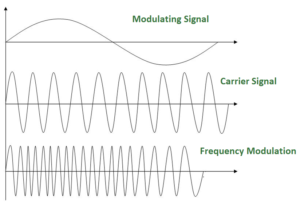
FM is normally implemented by using a voltage-controlled oscillator as with FSK. The frequency of the oscillator changes according to the input voltage which is the amplitude of the modulating signal.
FM bandwidth:
- The bandwidth of a frequency modulated signal varies with both deviation and modulating frequency.
If modulating frequency (Mf) 0.5, wide band Fm signal. - For a narrow band Fm signal, bandwidth required is twice the maximum frequency of the modulation, however for a wide band Fm signal the required bandwidth can be very much larger, with detectable sidebands spreading out over large amounts of the frequency spectrum.
Phase Modulation: PM
- Only phase is varied to reflect the change of amplitude in modulating signal
- Require simpler hardware than FM
So it can be said, the modulation in which the phase of the carrier wave is varied according to the instantaneous amplitude of the modulating signal keeping amplitude and frequency as constant. The figure below shows the concept of frequency modulation:
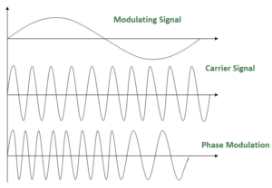
- Use in some systems as an alternative to FM.
- Phase modulation is practically similar to Frequency Modulation, but in Phase modulation frequency of the carrier signal is not increased. It is normally implemented by using a voltage-controlled oscillator along with a derivative. The frequency of the oscillator changes according to the derivative of the input voltage which is the amplitude of the modulating signal.
PM bandwidth:
- For small amplitude signals, PM is similar to amplitude modulation (AM) and exhibits its unfortunate doubling of baseband bandwidth and poor efficiency.
- For a single large sinusoidal signal, PM is similar to FM, and its bandwidth is approximately, 2 (h+1) Fm where h= modulation index.
Pulse Amplitude Modulation (PAM)
One analog-to-digital conversion method. PAM has some applications, but it is not used by itself in data communication. However, it is the first step in another very popular conversion method called pulse code modulation.
Quantized PAM
- Quantization
Method of assigning integral values in a specific range to sampled instance.
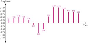
Quantizing by using sign and magnitude

Pulse Code Modulation(PCM)
PCM modifies the pulses created by PAM to create a completely digital signal.

Question: What sampling rate is needed for a signal with a bandwidth of 10,000 Hz (1000 to 11,000 Hz)?
The sampling rate must be twice the highest frequency in the signal:
Sampling rate = 2 x (11,000) = 22,000 samples/s
More Question: We want to digitize the human voice. What is the bit rate, assuming 8 bits per sample? The human voice normally contains frequencies from 0 to 4000 Hz.
Sampling rate = 4000 x 2 = 8000 samples/s
Bit rate = sampling rate x number of bits per sample
= 8000 x 8 = 64,000 bps = 64 Kbps
PPM & Delta Modulation
Pulse position modulation (PPM)
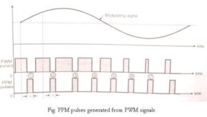
- In PPM the amplitude and width of the pulses is kept constant but the position of each pulse is varied accordance with the amplitudes of the sampled value of the modulating signal.
- The position of the pulses is changed with respect to the position of reference pulses.
- The PPM pulses can be derived from the PWM pulses. With the increase in the modulating voltage the PPM pulse shift further with respect to reference.
- The vertical dotted lines drawn in Fig are treated as reference lines to measure the shift in position of PPM pulses. The PPM pulses marked 1, 2 and 3 in fig go away from their respective reference lines.
- This is corresponding to increase in the modulating signal amplitude. Then as the modulating voltage decreases the PPM pulses 4,5,6,7 come progressively closer to their reference lines.
Delta modulation (DM or Δ-modulation) is an analog-to-digital and digital-to-analog signal conversion technique used for transmission of voice information where quality is not of primary importance. DM is the simplest form of differential pulse-code modulation (DPCM) where the difference between successive samples is encoded into n-bit data streams. In delta modulation, the transmitted data is reduced to a 1-bit data stream.
Its main features are:
| | the analog signal is approximated with a series of segments | |
| | each segment of the approximated signal is compared to the original analog wave to determine the increase or decrease in relative amplitude | |
| | the decision process for establishing the state of successive bits is determined by this comparison | |
| | only the change of information is sent, that is, only an increase or decrease of the signal amplitude from the previous sample is sent whereas a no-change condition causes the modulated signal to remain at the same 0 or 1 state of the previous sample. | |
|
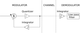
To achieve high signal-to-noise ratio, delta modulation must use oversampling techniques, that is, the analog signal is sampled at a rate several times higher than the Nyquist rate. Derived forms of delta modulation are continuously variable slope delta modulation, delta-sigma modulation, and differential modulation. The Differential Pulse Code Modulation is the super set of DM. Principle Rather than quantizing the absolute value of the input analog waveform, delta modulation quantizes the difference between the current and the previous step, as shown in the block diagram in Fig. 1.
Fig. 1 – Block diagram of a Δ-modulator/demodulator The modulator is made by a quantizer which converts the difference between the input signal and the average of the previous steps. In its simplest form, the quantizer can be realized with a comparator referenced to 0 (two levels quantizer), whose output is 1 or 0 if the input signal is positive or negative. The demodulator is simply an integrator (like the one in the feedback loop) whose output rises or falls with each 1 or 0 received. The integrator itself constitutes a low-pass filter. |
||

0 Comments