Interconnection Structure Overview
- The collection of paths connecting the various modules is called the interconnection structure.
- The preceding list defines the data to be exchanged. The interconnection structure must support the following types of transfers:
- Memory to processor: The processor reads an instruction or a unit of data from memory
- Processor to memory: The processor writes a unit of data to memory
- I/O to processor: The processor reads data from an I/O device via an I/O module
- Processor to I/O: The processor sends data to the I/O device
- I/O to or from memory: For these two cases, an I/O module is allowed to exchange data directly with memory, without going through the processor, using direct memory access (DMA)
BUS Interconnection
- A bus is a communication pathway connecting two or more devices
- It is a shared transmission medium
- Consists of multiple communication pathways, or lines, each line is capable of transmitting signals representing binary 1 and binary 0
- Multiple devices connect to the bus, and a signal transmitted by any one device is available for reception by all other devices attached to the bus
- If two devices transmit during the same time period, their signals will overlap and become garbled
- Only one device at a time can successfully transmit
- A bus that connects major computer components (processor, memory, I/O) is called a system bus
Bus Interconnection Schemes
1. Single Bus
Single Bus Problems:
- Lots of devices on one bus leads to:
Propagation delays:
- Long data paths mean that co-ordination of bus use can adversely affect performance
- Bus may become bottleneck if aggregate data transfer approaches bus capacity
- Most systems use multiple buses to overcome these problems
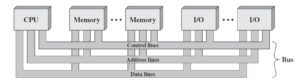
BUS Structure
- A system bus consists, typically, of from about 50 to hundreds of separate lines
- Each line is assigned a particular meaning or function
- Any bus the lines can be classified into three functional groups: data, address, and control lines
- There may be power distribution lines that supply power to the attached modules
DATA BUS
- The data lines provide a path for moving data among system modules
– These lines, collectively, are called the data bus
- The data bus may consist of 32, 64, 128, or even more separate lines, the number of lines being referred to as the width of the data bus
- Because each line can carry only 1 bit at a time, the number of lines determines how many bits can be transferred at a time
- Width: If the data bus is 32 bits wide and each instruction is 64 bits long, then the processor must access the memory module twice during each instruction cycle
ADDRESS BUS
- The address lines are used to designate the source or destination of the data on the data bus
- For example, if the processor wishes to read a word (8, 16, or 32 bits) of data from memory, it puts the address of the desired word on the address lines
- The width of the address bus determines the maximum possible memory capacity of the system.
- Typically, the higher-order bits are used to select a particular module on the bus, and the lower-order bits select a memory location or I/O port within the module
- For example, on an 8-bit address bus, address 01111111 and below might reference locations in a memory module (module 0) with 128 words of memory, and address
10000000 and above refer to devices attached to an I/O module (module 1)
CONTROL BUS
- The control lines are used to control the access to and the use of the data and address lines
- Control signals transmit both command and timing information among system modules
- Timing signals indicate the validity of data and address information
- Command signals specify operations to be performed
- Typical control lines include:
- Memory write, Memory read, I/O write, I/O read, Transfer ACK, Bus request, Bus grant, Interrupt request, Interrupt ACK, Clock, Reset
Interconnection set of components or modules
A computer consists of a set of components or modules of three basic types (processor, memory, I/O) that communicate with each other. In effect, a computer is a network of basic modules. Thus, there must be paths for connecting the modules. The collection of paths connecting the various modules is called the interconnection structure. The design of this structure will depend on the exchanges that must be made among modules.
The below figure suggests the types of exchanges that are needed by indicating the major forms of input and output for each module type.
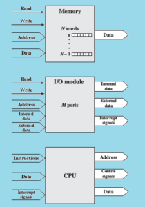
Memory: Typically, a memory module will consist of N words of equal length. Each word is assigned a unique numerical address (0, 1, . . . , N – 1). A word of data can be read from or written into the memory. The nature of the operation is indicated by read and write control signals. The location for the operation is specified by an address.
I/O module: From an internal (to the computer system) point of view, I/O is functionally similar to memory. There are two operations, read and write. Further, an I/O module may control more than one external device. We can refer to each of the interfaces to an external device as a port and give each a unique address (e.g., 0, 1, . . . , M – 1). In addition, there are external data paths for the input and output of data with an external device. Finally, an I/O module may be able to send interrupt signals to the processor.
Processor: The processor reads in instructions and data, writes out data after processing, and uses control signals to control the overall operation of the system. It also receives interrupt signals.
Bus Interconnection Schemes
2. Multiple-Bus
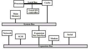
Figure: Traditional bus architecture
SCSI : small computer system interface to support local disk drives, CD-ROMs, and other peripherals
Serial: serial port to support a printer or scanner
It is possible to connect I/O controllers directly onto the system bus. A more efficient solution is to make use of one or more expansion buses for this purpose o Allows system to support wide variety of I/O devices o Insulates memory-to-process traffic from I/O traffic.
Bus Arbitration
- More than one module may control the bus
- g. CPU or DMA controller
- Only one module may control bus at one time Arbitration may be centralised or distributed
- Centralised:
- Single hardware device controlling bus access
- Bus Controller
- Arbiter
- May be part of CPU or separate Distributed:
- Each module may claim the bus
- Control logic on all modules
Timing
- Defines co-ordination of events on bus
Synchronous Bus Operation
— Events determined by clock signals
— Control Bus includes clock line
— A single 1-0 is a bus cycle
— All devices can read clock line
— Usually sync on leading edge
— Usually a single cycle for an event
Asynchronous Bus Operation
- Data transfer control on the bus is based on the use of a handshake between the master and the slave
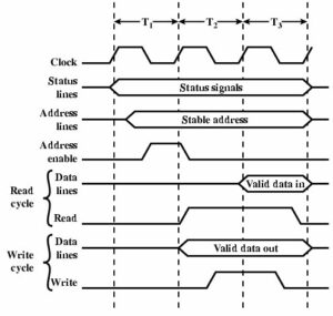
System Bus Read Cycle
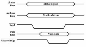
- Processor places address and status signals on the bus
- Issues Read command after these signals stabilize indicating presence of valid address and control signals
- Appropriate memory decodes the address and responds by placing data on the data line
- Once data lines have stabilized, memory module asserts the Acknowledge line to signal the processor that data are available
- Once data is read by the master, it deasserts the Read signal
- The memory module drops the data and acknowledge lines
- The master removes the address information.
System Bus Write Cycle
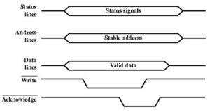
- Master places the data on the data line at the same time as status and address lines
- Memory module responds to the write command by copying data
- Memory module then assert the acknowledge line
- The master drops the write signal and memory module drops the acknowledge signal
0 Comments