Analog and Digital Signals
An analog signal is any continuous signal for which the time varying feature of the signal is a representation of some other time varying quantity i.e., analogous to another time varying Signal.

Signals can be analog or digital. Analog signals can have an infinite number of values in a range; digital signals can have only a limited number of values.
Digital to Analog Modulation

Digital-to-analog modulation: the process of changing one of the characteristics of an analog signal based on the information in a digital signal “Forget me not”: characteristics of a sine wave are amplitude, frequency, phase. Carrier Signal.
- Sender
- Produce a high-frequency signal that acts as a basis for the information signal => carrier signal
- Modulate the carrier signal to reflect the digital information. The information signal is called the modulating signal
- Receiver
- Tune in the carrier frequency to receive
Analog to Digital and Digital to Analog Communications
- Analog Communication :
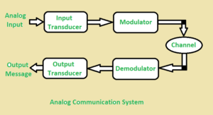
In analog communication the data is transferred with the help of analog signal in between transmitter and receiver. Any type of data is transferred in analog signal. Any data is converted into electric form first and after that it is passed through communication channel. Analog communication uses a continuous signal which varies in amplitude, phase, or some other property with time in proportion to that of a variable.
The below figure illustrates the Analog Communication System :
- Digital Communication :
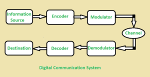
In digital communication digital signal is used rather than analog signal for communication in between the source and destination. They digital signal consists of discrete values rather than continuous values. In digital communication physical transfer of data occurs in the form of digital bit stream i.e 0 or 1 over a point-to-point or point-to-multipoint transmission medium. In digital communication the digital transmission data can be broken into packets as discrete messages which is not allowed in analog communication.
The below figure illustrates the Digital Communication System :
Difference between Analog Communication and Digital Communication :
| S .No. | ANALOG COMMUNICATION | DIGITAL COMMUNICATION |
| 01. | In analog communication analog signal is used for information transmission. | In digital communication digital signal is used for information transmission. |
| 02. | Analog communication uses analog signal whose amplitude varies continuously with time from 0 to 100. | Digital communication uses digital signal whose amplitude is of two levels either Low i.e., 0 or either High i.e., 1. |
| 03. | It gets affected by noise highly during transmission through communication channel. | It gets affected by noise less during transmission through communication channel. |
| 04. | In analog communication only limited number of channels can be broadcasted simultaneously. | It can broadcast large number of channels simultaneously. |
| 05. | In analog communication error Probability is high. | In digital communication error Probability is low. |
| 06. | In analog communication noise immunity is poor. | In digital communication noise immunity is good. |
| 07. | In analog communication coding is not possible. | In digital communication coding is possible. Different coding techniques can be used to detect and correct errors. |
| 08. | Separating out noise and signal in analog communication is not possible. | Separating out noise and signal in digital communication is possible. |
| 09. | Analog communication system is having complex hardware and less flexible. | Digital communication system is having less complex hardware and more flexible. |
| 10. | In analog communication for multiplexing
Frequency Division Multiplexing (FDM) is used.
|
In Digital communication for multiplexing
Time Division Multiplexing (TDM) is used.
|
| 11. | Analog communication system is low cost. | Digital communication system is high cost. |
| 12. | It requires low bandwidth. | It requires high bandwidth. |
| 13. | Power consumption is high. | Power consumption is low. |
| 14. | It is less portable. | Portability is high. |
| 15. | No privacy or privacy is less so not highly secured. | Privacy is high so it is highly secured. |
| 16. | Not assures an accurate data transmission. | It assures a more accurate data transmission. |
| 17. | Synchronization problem. | Synchronization problem is easier. |
Bit Rate vs. Baud Rate
Bit rate is the number of bits per second
- More important in speaking of computer efficiency
Baud rate is the number of signal units per second that are required to represent those bits
- More important in speaking of data transmission
Determine the bandwidth required to send the signal
Analogy in transportation: a baud is analogous to a car while a bit is analogous to a passenger (1: male, 0: female). The number of cars determines the traffic; that of passengers does not.
Baud Rate Example
An analog signal carries 4 bits in each signal unit. If 1000 signal units are sent per second, find the baud rate and the bit rate
Baud rate = 1000 bauds per second (baud/s)
Bit rate = 1000 x 4 = 4000 bps
The bit rate of a signal is 3000. If each signal unit carries 6 bits, what is the baud rate?
Baud rate = 3000 / 6 = 500 baud/s
Digital-Analog Modulation Schemes
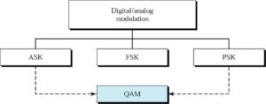
Quadrature shift modulation
All a,f,p changes combined
Amplitude Shift Keying (ASK)
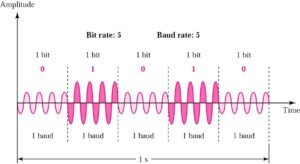
Peak amplitude during each bit duration is constant
- Disadvantage
- Highly susceptible to noise interference because ASK relies on amplitude to differentiate between 1 and 0
- Need a great gap between amplitude values so that noise can be detected and removed
- OOK (on/off keying)
- A popular ASK technique
- Zero voltage represent a bit value (e.g., 0)
- Save energy in transmitting information
- On voice-grade line, up to 1200bps
- Used to transmit digital data over optical fiber
Frequency Shift Keying (FSK)
Only frequency is varied to represent binary 1 or 0
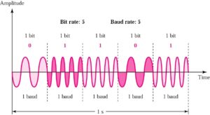
FSK vs. ASK
- FSK
- Less susceptible to error
- On voice-grade lines, up to 1200bps
- Commonly used for high-freq (3-30 Mhz) radio
– Also used at even high freq on LANs that use coaxial cable
Phase Shift Keying (PSK)
- Only phase is varied to represent 1 or 0
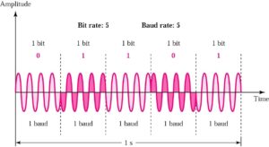
- 2-PSK: only 2 phase values are used, each for 1 or 0
4-PSK
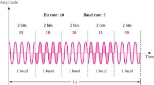
Note: PSK is no susceptible to the noise degradation that affects ASK or to the bandwidth limitations of FSK
Modulation device is not able to distinguish small differences in phase => limit BitRate
Why not combine PSK and ASK: x variations in phase with y variations in amplitude result in xy variations => increase bit rate
8-QAM
Quadrature amplitude modulation can be used with a variety of different formats: 8QAM, 16QAM, 64QAM, 128QAM, 256QAM, but there are performance differences and trade-offs
QAM, quadrature amplitude modulation provides some significant benefits for data transmission. As 16QAM transitions to 64QAM, 64QAM to 256 QAM and so forth, higher data rates can be achieved, but at the cost of the noise margin.
Many data transmission systems migrate between the different orders of QAM, 16QAM, 32QAM, etc., dependent upon the link conditions. If there is a good margin, higher orders of QAM can be used to gain a faster data rate, but if the link deteriorates, lower orders are used to preserve the noise margin and ensure that a low bit error rate is preserved.
Accordingly there is a balance to be made between the data rate and QAM modulation order, power and the acceptable bit error rate. Whilst further error correction can be introduced to mitigate any deterioration in link quality, this will also decrease the data throughput.
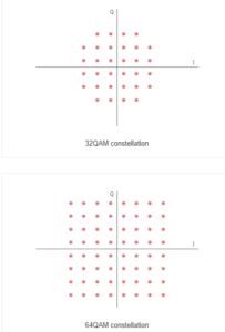
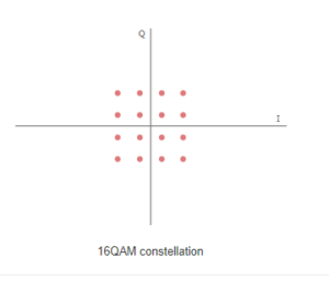
The diagrams below show constellation diagrams for a variety of formats of modulation:

QAM formats and applications
For some systems the order of the modulation format is fixed, but in others where there is a two way link, it is possible to adapt the order of the modulation to obtain the best throughput for the given link conditions. The level of error correction used is also altered. In this way, changing the modulation order, and the error correction, the data speed can be optimised whilst maintaining the required error rate.
For domestic broadcast applications for example, 64 QAM and 256 QAM are often used in digital cable television and cable modem applications. The order of the QAM modulation has to be set at the transmitter, because the transmission is only one way, and in addition to this, there are thousands of receivers, making it impossible to have a dynamically adaptive form of modulation.
Constellation diagrams for QAM
The constellation diagrams show the different positions for the states within different forms of QAM, quadrature amplitude modulation. As the order of the modulation increases, so does the number of points on the QAM constellation diagram.
Compare among ASK , PSK & FSK .
| Parameters | ASK | FSK | PSK |
|---|---|---|---|
| Variable characteristics | Amplitude | Frequency | Phase |
| Bandwidth | Is proportional to signal rate (B =(1+d)S),d is due to modulation & filtering ,lies between 0 & 1. | B=(1+d)×S+2Δf | B=(1+d)×S |
| Noise immunity | low | High | High |
| Complexity | Simple | Moderately complex | Very complex |
| Error probability | High | Low | Low |
| Performance in presence of noise | Poor | Better than ASK | Better than FSK |
| Bit rate | Suitable up to 100 bits/sec | Suitable upto about 1200 bits/sec | Suitable for high bit rates |

0 Comments