Networking
- Network
A network is a set of devices (often referred to as nodes) connected by links. A node can be a computer, printer, or any other device capable of sending and/or receiving data generated by other nodes on the network.
- Network criteria
- Performance
- reliability
– security
Point-to-Point Connection
A point-to-point line configuration provides a dedicated link between two devices. The entire capacity of the channel is reserved for transmission between those two devices.

Multi-point Connection
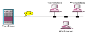
A multipoint line configuration is one in which more than two specific devices share a single link. In a multipoint environment, the capacity of the channel is shared, either spatially or temporally.
Physical Topologies
The topology of a network is the geometric representation of the relationship of all links and linking devices to one other. Two or more devices connect to a link; two or more links form a topology.

Mesh Topology
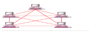
In a mesh topology, every device has a dedicated point-to-point link to every other device. The term dedicated means that the link carries traffic only between the two devices it connects.
Advantages
- The use of a dedicated links guarantees that each connection can carry its own load, thus eliminating the traffic problems that can occur when links must be shared by multiple devices.
- A mesh topology is robust. If one link becomes unusable, it does not incapacitate the entire system.
- When every message sent travels along a dedicated link, only the intended recipient sees it.
Physical boundaries prevent other users from gaining access to messages.
- Point-to Point links make fault identification and fault isolation
Disadvantages
- A big amount of cabling and a big number of I/O ports required, i.e, the hardware required can be very expensive.
- Because every device must be connected to every other device, installation and reconfiguration are difficult.
- For these reasons a mesh topology is usually implemented in a limited fashion.
- For example, as a backbone connecting the main computers to a hybrid network that can include several other topologies.
Star Topology
In a star topology, each device has a dedicated point-to-point link only to a central controller, usually called a hub. A star topology does not allow direct traffic between devices. If one device wants to send data to another, it sends the data to the controller, which then relays the data to the other connected device.

Advantages
- It is easy to install and reconfigure
- The star topology is robust. If one link fails, only that link is affected. This factor also lends itself to easy fault identification and fault isolation.
Disadvantages
- A big amount of cabling and a big number of I/O ports required, i.e, the hardware required can be very expensive.
Note: Star topology requires far less cable than Mesh topology.
Bus Topology
In a bus topology one long cable acts as a backbone to link all the devices in the network. Nodes are connected to the bus cable by drop lines and taps. A drop line is a connection running between the device and the main cable. A tap is a connector that either splices into the main cable or punctures the sheathing of a cable to create a contact with the metallic core.

Advantages
- Easy to install
- Bus topology uses less cabling than mesh, star, or tree topologies.
Disadvantages
- Difficult reconfiguration and fault isolation. A bus is usually designed to be optimally efficient at installation. It can therefore be difficult to add a new devices.
- A fault or break in the bus cable stops all transmission, even between devices on the same side of the problem. The damaged area reflects signals back in the direction of origin, creating noise in both directions.
Ring Topology
In a ring topology, each device has a dedicated point-to-point line configuration only with the two devices on either side of it.

Advantages
- Easy to install and reconfigure. To add or delete a device require only two connections.
- Easy fault isolation
Disadvantages
- A break in the ring (such as a disabled station) can disable the entire network. Categories of Networks
Category Of Networks

Local Area Networks
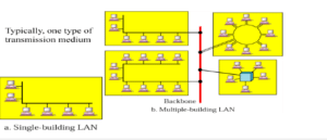
A Local Area Network (LAN) is a private network that connects computers and devices within a limited area like a residence, an office, a building or a campus. On a small scale, LANs are used to connect personal computers to printers.
Metropolitan Area Networks
A Metropolitan Area Network (MAN) is a larger network than LAN. It often covers multiple cities or towns. It is quiet expensive and a single organization may not have own it.

Wide Area Networks
A Wide Area Network (WAN) is a much larger network than LAN and MAN. It often covers multiple contries or contenants. It is quiet expensive and a single organization may not have own it. Satellite is used to manage WAN.

Following are the important differences between LAN, MAN and WAN.
| Sr. No. | Key | LAN | MAN | WAN |
|---|---|---|---|---|
| 1 | Definition | LAN stands for Local Area Network. | MAN stands for Metropolitan Area Network. | WAN stands for Wide Area Network. |
| 2 | Ownership | LAN is often owned by private organizations. | MAN ownership can be private or public. | WAN ownership can be private or public. |
| 3 | Speed | LAN speed is quiet high. | MAN speed is average. | WAN speed is lower than that of LAN. |
| 4 | Delay | Network Propagation Delay is short in LAN. | Network Propagation Delay is moderate in MAN. | Network Propagation Delay is longer in WAN. |
| 5 | Congestion | LAN has low congestion as compared to WAN. | MAN has higher congestion than LAN. | WAN has higher congestion than both MAN and LAN. |
| 6 | Fault Tolerance | Fault Tolerance of LAN is higher than WAN. | Fault Tolerance of MAN is lower than LAN. | Fault Tolerance of WAN is lower than both LAN and MAN. |
| 7 | Maintenance | Designing and maintaining LAN is easy and less costly than WAN. | Designing and maintaining WAN is complex and more costly than LAN. | Designing and maintaining WAN is complex and more costly than both LAN and MAN. |
Network Models
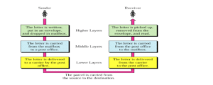
Sending a Letter
Internet Model
The TCP/IP model, sometimes referred to as a protocol stack, can be considered a condensed version of the OSI model.
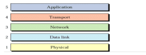
Internet uses TCP/IP protocol suite, also known as Internet suite. This defines Internet Model which contains four layered architecture. OSI Model is general communication model but Internet Model is what the internet uses for all its communication. The internet is independent of its underlying network architecture so is its Model. This model has the following layers:
- Application Layer: This layer defines the protocol which enables user to interact with the network. For example, FTP, HTTP etc.
- Transport Layer: This layer defines how data should flow between hosts. Major protocol at this layer is Transmission Control Protocol (TCP). This layer ensures data delivered between hosts is in-order and is responsible for end-to-end delivery.
- Internet Layer: Internet Protocol (IP) works on this layer. This layer facilitates host addressing and recognition. This layer defines routing.
- Link Layer: This layer provides mechanism of sending and receiving actual data. Unlike its OSI Model counterpart, this layer is independent of underlying network architecture and hardware.
Peer to Peer Process
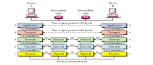
Physical Layer
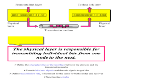
The lowest layer of the OSI Model is concerned with electrically or optically transmitting raw unstructured data bits across the network from the physical layer of the sending device to the physical layer of the receiving device. It can include specifications such as voltages, pin layout, cabling, and radio frequencies. At the physical layer, one might find “physical” resources such as network hubs, cabling, repeaters, network adapters or modems.
Data Link Layer

At the data link layer, directly connected nodes are used to perform node-to-node data transfer where data is packaged into frames. The data link layer also corrects errors that may have occurred at the physical layer.
The data link layer encompasses two sub-layers of its own. The first, media access control (MAC), provides flow control and multiplexing for device transmissions over a network. The second, the logical link control (LLC), provides flow and error control over the physical medium as well as identifies line protocols.
Protect Your Network Layers with Forcepoint NGFW

Network Layer
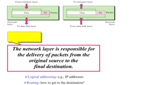
The network layer is responsible for receiving frames from the data link layer, and delivering them to their intended destinations among based on the addresses contained inside the frame. The network layer finds the destination by using logical addresses, such as IP (internet protocol). At this layer, routers are a crucial component used to quite literally route information where it needs to go between networks.
Transport Layer

The transport layer manages the delivery and error checking of data packets. It regulates the size, sequencing, and ultimately the transfer of data between systems and hosts. One of the most common examples of the transport layer is TCP or the Transmission Control Protocol.
Application Layer

At this layer, both the end user and the application layer interact directly with the software application. This layer sees network services provided to end-user applications such as a web browser or Office 365. The application layer identifies communication partners, resource availability, and synchronizes communication.
Example
A node with physical address 10 sends a frame to a node with physical address 87. The two nodes are connected by a link. At the data link level this frame contains physical addresses in the header. These are the only addresses needed. The rest of the header contains other information needed at this level. The trailer usually contains extra bits needed for error
The Open Systems Interconnection(OSI) Model Defined
The OSI Model (Open Systems Interconnection Model) is a conceptual framework used to describe the functions of a networking system. The OSI model characterizes computing functions into a universal set of rules and requirements in order to support interoperability between different products and software. In the OSI reference model, the communications between a computing system are split into seven different abstraction layers: Physical, Data Link, Network, Transport, Session, Presentation, and Application.
Created at a time when network computing was in its infancy, the OSI was published in 1984 by the International Organization for Standardization (ISO). This model has seven layers:
- Application Layer: This layer is responsible for providing interface to the application user. This layer encompasses protocols which directly interact with the user.
- Presentation Layer: This layer defines how data in the native format of remote host should be presented in the native format of host.
- Session Layer: This layer maintains sessions between remote hosts. For example, once user/password authentication is done, the remote host maintains this session for a while and does not ask for authentication again in that time span.
- Transport Layer: This layer is responsible for end-to-end delivery between hosts.
- Network Layer: This layer is responsible for address assignment and uniquely addressing hosts in a network.
- Data Link Layer: This layer is responsible for reading and writing data from and onto the line. Link errors are detected at this layer.
- Physical Layer: This layer defines the hardware, cabling wiring, power output, pulse rate etc.
Bit-to-Signal Transformation
To be transmitted, data must be transformed to electromagnetic signals.
Bit-Rate Control
- The transmission medium provides the upper limit on data rate, the physical layer controls it Bit Synchronization
- The physical layer provides clocking mechanisms to control the timing of bit transfer Multiplexing
- A physical link may need to be divided into logical channels, each used by a transmission, for better efficiency
Circuit Switching
Allowing pairs of nodes to have their dedicated links is a function of the physical layer Signals
- The main function of the physical layer is moving information in the form of electromagnetic signals across a transmission media.
- Information can be in the form of data, voice, picture, and so on.
- Generally the information usable to a person or application is not in a form that can be transmitted over a network.
- Data stream of 1s and 0s must be turned into energy in the form of electromagnetic signals.

0 Comments