Computer Graphics Window:
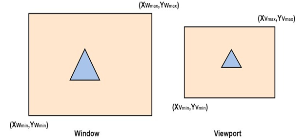
The method of selecting and enlarging a portion of a drawing is called windowing. The area chosen for this display is called a window. The window is selected by world-coordinate. Sometimes we are interested in some portion of the object and not in full object. So we will decide on an imaginary box. This box will enclose desired or interested area of the object. Such an imaginary box is called a window.
Viewport: An area on display device to which a window is mapped [where it is to displayed].
Basically, the window is an area in object space. It encloses the object. After the user selects this, space is mapped on the whole area of the viewport. Almost all 2D and 3D graphics packages provide means of defining viewport size on the screen. It is possible to determine many viewports on different areas of display and view the same object in a different angle in each viewport.
The size of the window is (0, 0) coordinate which is a bottom-left corner and toward right side until window encloses the desired area. Once the window is defined data outside the window is clipped before representing to screen coordinates. This process reduces the amount of data displaying signals. The window size of the Tektronix 4.14 tube in Imperial College contains 4.96 points horizontally and 3072 points vertically.
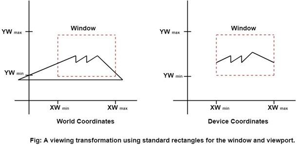
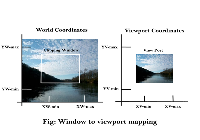
Viewing transformation or window to viewport transformation or windowing transformation: The mapping of a part of a world-coordinate scene to device coordinates is referred to as a viewing transformation etc.
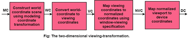
Viewing transformation in several steps:
- First, we construct the scene in world coordinate using the output primitives and attributes.
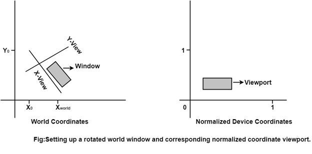
- To obtain a particular orientation, we can set up a 2-D viewing coordinate system in the window coordinate plane and define a window in viewing coordinates system.
- Once the viewing frame is established, are then transform description in world coordinates to viewing coordinates.
- Then, we define viewport in normalized coordinates (range from 0 to 1) and map the viewing coordinates description of the scene to normalized coordinates.
At the final step, all parts of the picture that (i.e., outside the viewport are dipped, and the contents are transferred to device coordinates).
By changing the position of the viewport: We can view objects at different locations on the display area of an output device as shown in fig:
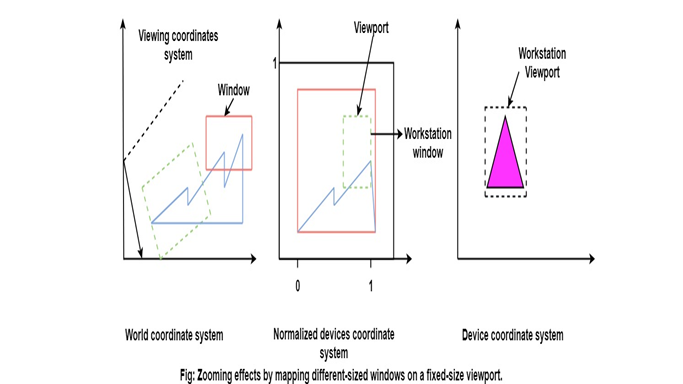
By varying the size of viewports: We can change the size and proportions of displayed objects. We can achieve zooming effects by successively mapping different-sized windows on a fixed-size viewport. As the windows are made smaller, we zoom in on some part of a scene to view details that are not shown with larger windows.
Computer Graphics Window to Viewport Co-ordinate Transformation
Once object description has been transmitted to the viewing reference frame, we choose the window extends in viewing coordinates and selects the viewport limits in normalized coordinates.
Object descriptions are then transferred to normalized device coordinates:
- We do this thing using a transformation that maintains the same relative placement of an object in normalized space as they had in viewing coordinates.
- If a coordinate position is at the center of the viewing window:
It will display at the center of the viewport. - Fig shows the window to viewport mapping. A point at position (xw, yw) in window mapped into position (xv, yv) in the associated viewport.
In order to maintain the same relative placement of the point in the viewport as in the window, we require:
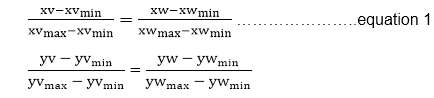
Solving these impressions for the viewport position (xv, yv), we have
xv=xvmin+(xw-xwmin)sx
yv=yvmin+(yw-ywmin)sy ………..equation 2
Where scaling factors are
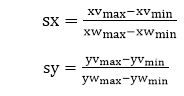
Equation (1) and Equation (2) can also be derived with a set of transformation that converts the window or world coordinate area into the viewport or screen coordinate area. This conversation is performed with the following sequence of transformations:
- Perform a scaling transformation using a fixed point position (xwmin,ywmin) that scales the window area to the size of the viewport.
- Translate the scaled window area to the position of the viewport. Relative proportions of objects are maintained if the scaling factors are the same (sx=sy).
From normalized coordinates, object descriptions are mapped to the various display devices.
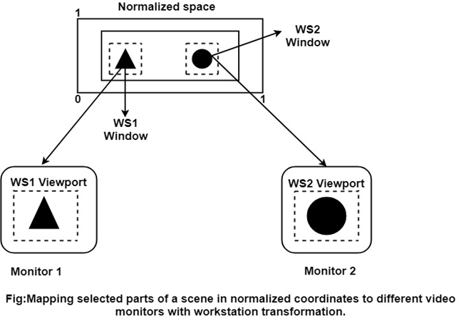
Any number of output devices can we open in a particular app, and three windows to viewport transformation can be performed for each open output device.
This mapping called workstation transformation (It is accomplished by selecting a window area in normalized space and a viewport area in the coordinates of the display device).
As in fig, workstation transformation to partition a view so that different parts of normalized space can be displayed on various output devices).
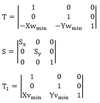
Matrix Representation of the above three steps of Transformation:
Step1:Translate window to origin 1
Tx=-Xwmin Ty=-Ywmin
Step2:Scaling of the window to match its size to the viewport
Sx=(Xymax-Xvmin)/(Xwmax-Xwmin)
Sy=(Yvmax-Yvmin)/(Ywmax-Ywmin)
Step3:Again translate viewport to its correct position on screen.
Tx=Xvmin
Ty=Yvmin
Above three steps can be represented in matrix form:
VT=T * S * T1
T = Translate window to the origin
S=Scaling of the window to viewport size
T1=Translating viewport on screen.
Viewing Transformation= T * S * T1
Advantage of Viewing Transformation:
We can display picture at device or display system according to our need and choice.
Note:
- World coordinate system is selected suits according to the application program.
- Screen coordinate system is chosen according to the need of design.
- Viewing transformation is selected as a bridge between the world and screen coordinate.
Computer Graphics Zooming
Zooming is a transformation often provided with an imaginary software. The transformation effectively scales down or blows up a pixel map or a portion of it with the instructions from the user. Such scaling is commonly implemented at the pixel level rather than at the coordinates level. A video display or an image is necessarily a pixel map, i.e., a collection of pixels which are the smallest addressable elements of a picture. The process of zooming replicates pixels along successive scan lines.
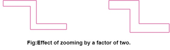
Example: for a zoom factor of two
Each pixel value is used four times twice on each of the two successive scan lines.
Figure shows the effect of zooming by a factor of 2.
Such integration of pixels sometimes involves replication using a set of ordered patterns, commonly known as Dithering.
The two most common dither types are:
- Ordered dither.
- Random dither.
There are widely used, especially when the grey levels (share of brightness) are synthetically generated.
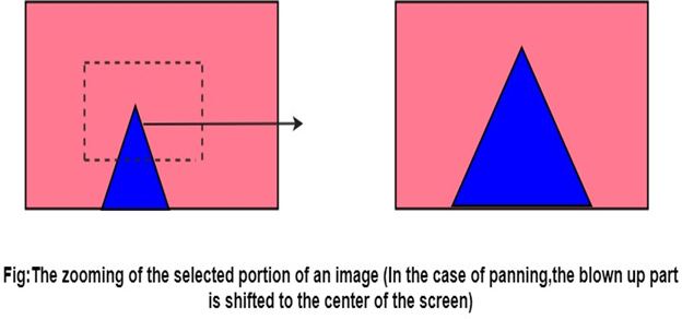
Computer Graphics Panning
The process of panning acts as a qualifier to the zooming transformation. This step moves the scaled up portion of the image to the center of the screen and depending on the scale factor, fill up the entire screen.
Advantage:
Effective increase in zoom area in all four direction even if the selected image portion (for zooming) is close to the screen boundary.
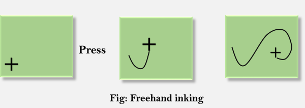
Inking:
If we sample the position of a graphical input device at regular intervals and display a dot at each sampled position, a trial will be displayed of the movement of the device.This technique which closely simulates the effect of drawing on paper is called Inking.
For many years the primary use of inking has been in conjunction with online character-recognition programs.
Scissoring:
In computer graphics, the deleting of any parts of an image which falls outside of a window that has been sized and laid the original vision ever. It is also called the clipping.
0 Comments