Interrupts in 8086 microprocessor
Interrupt is a process of generating a temporary halt throughout program execution and permits peripheral devices to access the microprocessor.
Microprocessor answers to these interrupts with an interrupt service routine (ISR), which is a short program or subroutine to instruct the microprocessor on how to handle the interrupt.
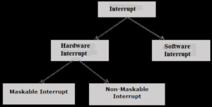
There are different types of interrupt in 8086:
Hardware Interrupts
Hardware interrupts are that type of interrupt which are caused by any peripheral device by sending a signal through a specified pin to the microprocessor.
The Intel 8086 has two hardware interrupt pins:
- NMI (Non-Maskbale Interrupt)
- INTR (Interrupt Request) Maskable Interrupt.
NMI: NMI is a single Non-Maskable Interrupt having higher priority than the maskable interrupt.
- It cannot be disabled (masked) by user using software.
- It is used by the processor to handle emergency conditions.
For example: It can be used to save program and data in case of power failure. An external electronic circuitry is used to detect power failure, and to send an interrupt signal to 8086 through NMI line.
INTR: The INTR is a maskable interrupt. It can be enabled/disabled using interrupt flag (IF). After receiving INTR from external device, the 8086 acknowledges through INTA signal.
It executes two consecutive interrupt acknowledge bus cycles.
Software Interrupt
A microprocessor can also be interrupted by internal irregular conditions like as overflow; division by zero; etc. A programmer can also interrupt microprocessor by inserting INT instruction at the chosen point in the program while debugging a program. Such an interrupt is called a software interrupt. The interrupt caused by an internal abnormal conditions also came under the heading of software interrupt.
Example of software interrupts are:
- TYPE 0 (division by zero)
- TYPE 1 (single step execution for debugging a program)
- TYPE 2 represents NMI (power failure condition)
- TYPE 3 (break point interrupt)
- TYPE 4 (overflow interrupt)
Interrupt pointer table for 8086

Fig: Interrupt pointer table for 8086
The 8086 can handle up to 256, hardware and software interrupts.
1KB memory performances as a table to contain interrupt vectors (or interrupt pointers), and it is called interrupt vector table or interrupt pointer table. The 256 interrupt pointers have been numbered from 0 to 255 (FF hex). The number assigned to an interrupt pointer is known as type of that interrupt. For example, Type 0, Type 1, Type 2,………..Type 255 interrupt.
Addressing modes of 8086
An operand which way is specified for an instruction in the accumulator, in a general-purpose register or in memory location, is called addressing mode.
The 8086 microprocessors have 8 addressing modes. Two addressing modes have been as long as for instructions which operate on register or immediate data.
These two addressing modes are:
Register Addressing: In register addressing, the operand is placed in one of the 16-bit or 8-bit general purpose registers.
Example
- MOV AX, CX
- ADD AL, BL
- ADD CX, DX
Immediate Addressing: In immediate addressing, the operand is specified in the instruction itself.
Example
- MOV AL, 35H
- MOV BX, 0301H
- MOV [0401], 3598H
- ADD AX, 4836H
The remaining 6 addressing modes specify the location of an operand which is placed in a memory.
These 6 addressing modes are:
Direct Addressing: In direct addressing mode, the operand’s offset is given in the instruction as an 8-bit or 16-bit displacement element.
Example
- ADD AL, [0102]
The instruction adds the content of the offset address 0102 to AL. the operand is placed at the given offset (0102) within the data segment DS.
Register Indirect Addressing: The operand’s offset is placed in any one of the registers BX, BP, SI or DI as specified in the instruction.
Example
- MOV AX, [BX]
It moves the contents of memory locations addressed by the register BX to the register AX.
Based Addressing: The operand’s offset is the sum of an 8-bit or 16-bit displacement and the contents of the base register BX or BP. BX is used as base register for data segment, and the BP is used as a base register for stack segment.
Effective address (Offset) = [BX + 8-bit or 16-bit displacement].
Example
- MOV AL, [BX+05]; an example of 8-bit displacement.
- MOV AL, [BX + 1346H]; example of 16-bit displacement.
Indexed Addressing: The offset of an operand is the sum of the content of an index register SI or DI and an 8-bit or 16-bit displacement.
Offset (Effective Address) = [SI or DI + 8-bit or 16-bit displacement]
Example
- MOV AX, [SI + 05]; 8-bit displacement.
- MOV AX, [SI + 1528H]; 16-bit displacement.
Based Indexed Addressing: The offset of operand is the sum of the content of a base register BX or BP and an index register SI or DI.
Effective Address (Offset) = [BX or BP] + [SI or DI]
Here, BX is used for a base register for data segment, and BP is used as a base register for stack segment.
Example
- ADD AX, [BX + SI]
- MOV CX, [BX + SI]
Based Indexed with Displacement: In this mode of addressing, the operand’s offset is given by:
Effective Address (Offset) = [BX or BP] + [SI or DI] + 8-bit or 16-bit displacement
Example
- MOV AX, [BX + SI + 05]; 8-bit displacement
- MOV AX, [BX + SI + 1235H]; 16-bit displacement
0 Comments