Part 3: Analog and Digital Signals: Time-Domain, Frequency, Bandwidth & Noise
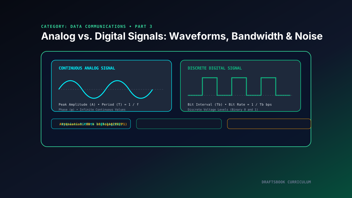
Lesson Overview & Learning Objectives
To be transmitted over a physical medium, data must be converted into physical electromagnetic signals. In data communications, signals are categorized into continuous Analog Signals and discrete Digital Signals. In this installment, we dissect the mathematical parameters of sine waves (amplitude, frequency, period, phase), apply Fourier analysis to decompose composite signals into frequency harmonics, examine the causes of transmission impairment (attenuation, distortion, thermal noise), and calculate theoretical maximum channel capacities via the Nyquist and Shannon theorems.
1. Anatomy of an Analog Sine Wave
The fundamental building block of all analog communication is the simple periodic sine wave, modeled mathematically as:
- Peak Amplitude (A): The absolute value of its highest intensity, proportional to the energy carried by the signal (measured in Volts).
- Frequency (f) & Period (T): Frequency is the rate of change with respect to time (cycles per second, in Hertz [Hz]). Period is the inverse: \(T = 1/f\).
- Phase (φ): The position of the waveform relative to time zero (measured in degrees or radians), representing a forward or backward shift in time.
2. Bandwidth: The Frequency Spectrum
According to Fourier Analysis, any composite signal can be decomposed into an infinite combination of simple sine waves with different frequencies, amplitudes, and phases.
The Bandwidth (B) of a composite signal is the difference between the highest and lowest frequencies contained within that signal:
For example, human voice telephony channels historically span from 300 Hz to 3400 Hz, yielding an effective voice bandwidth of \(3400 - 300 = 3100 ext{ Hz}\) (3.1 kHz).
3. Channel Capacity: Nyquist vs. Shannon Theorems
Nyquist Bit Rate (Noiseless Channel)
For an ideal channel with zero noise, Harry Nyquist proved that the maximum data rate is bounded purely by bandwidth \(B\) and discrete signal levels \(L\):
Increasing signal voltage levels \(L\) increases bit throughput, but requires higher receiver precision.
Shannon Capacity (Noisy Real-World Channel)
Claude Shannon extended information theory to real channels corrupted by Gaussian thermal noise:
No matter how many signal levels you design, the physical Signal-to-Noise Ratio (SNR) sets an insurmountable upper limit on error-free bit rate.
Related reading
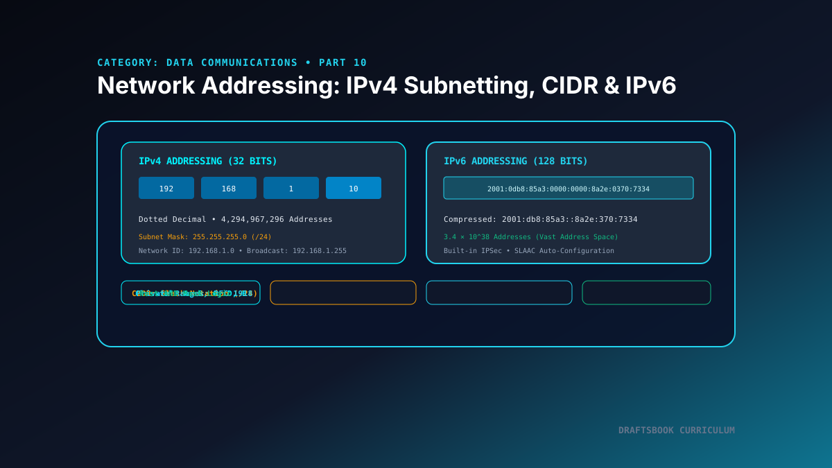
Part 10: Network Layer Addressing: IPv4 Subnetting, CIDR & IPv6 Architecture
Master logical network addressing: explore IPv4 classful ranges, CIDR slash notation, subnet mask bitwise ANDing, and modern 128-bit IPv6 architecture.
By Md. Harun-Or-Roshid
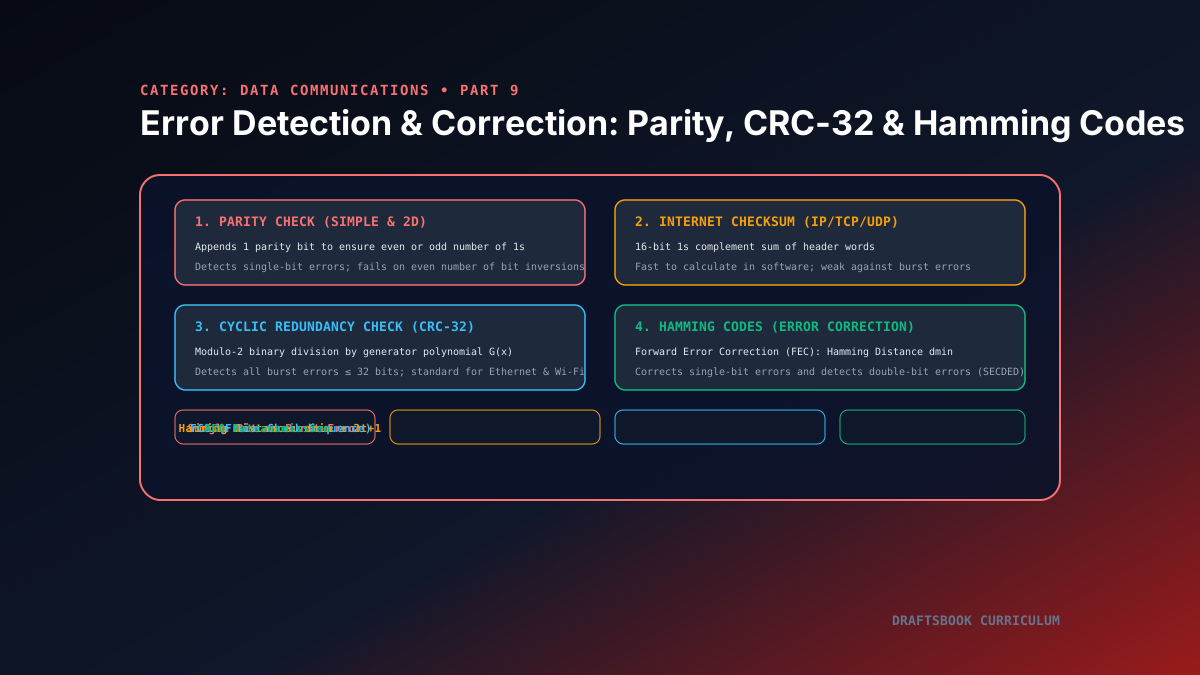
Part 9: Error Detection and Correction: Parity, Checksums, CRC-32 & Hamming
A deep dive into data integrity: comparing simple parity, Internet Checksums, Cyclic Redundancy Checks (CRC-32), and Hamming forward error correction.
By Md. Harun-Or-Roshid
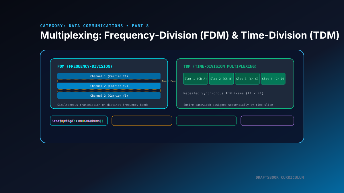
Part 8: Multiplexing Techniques: Frequency-Division (FDM) & Time-Division (TDM)
A comprehensive guide to signal multiplexing: analyzing Frequency-Division (FDM), Synchronous and Statistical Time-Division (TDM), and optical WDM.
By Md. Harun-Or-Roshid
Part 7: Pulse Modulation & Companding: PAM, PWM, PPM, PCM & Quantization
Explore analog-to-digital signal conversion: comparing PAM, PWM, PPM, Pulse Code Modulation (PCM) sampling, quantization error, and µ-law/A-law companding.
By Md. Harun-Or-Roshid