Part 4: Instruction Pipelining: The Classic 5-Stage RISC Processor Datapath
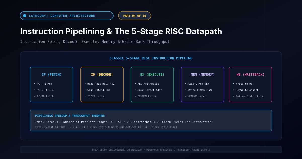
Instruction Pipelining & Hardware Throughput
If a processor must wait for an entire instruction to complete before fetching the next, 80% of its internal silicon hardware sits idle at any given millisecond. Instruction Pipelining is an implementation technique where multiple instructions are overlapped in execution, analogous to an automotive assembly line. In a 5-stage pipeline, five different instructions occupy five distinct processing stages simultaneously. In this article, we dissect the classic 5-Stage RISC Pipelined Datapath, formulate the mathematical speedup equations, and analyze the role of inter-stage pipeline registers.
1. The Assembly Line Analogy & Pipelining Throughput
Consider a laundry facility with four sequential steps: Wash (30 min), Dry (40 min), Fold (20 min), and Stash (20 min). Washing a single load of laundry takes $30+40+20+20 = 110\text{ minutes}$.
- Sequential Processing: 4 loads take $4 \times 110\text{ min} = 440\text{ minutes}$ (over 7 hours).
- Pipelined Processing: As soon as Load 1 moves to the dryer, Load 2 enters the washer. Once the pipeline fills, a fresh clean load exits every 40 minutes (the duration of the slowest stage).
Key Architectural Invariant: Pipelining does not reduce the individual latency required to execute a single instruction; rather, it exponentially increases total instruction throughput (instructions retired per second).
2. The Classic 5-Stage RISC Architecture
1. IF
Instruction Fetch
Read instruction from I-Cache pointed to by PC. Increment PC = PC + 4.
2. ID
Instruction Decode
Decode opcode; read source registers $Rs1, Rs2$; sign-extend immediate.
3. EX
Execute / ALU
Perform arithmetic op, calculate memory effective address, or test branch.
4. MEM
Memory Access
Read from or write to D-Cache for load and store operations.
5. WB
Write-Back
Commit ALU or memory result back into destination register $Rd$.
3. Inter-Stage Pipeline Registers (Latches)
In an unpipelined datapath, signals flow continuously through combinational logic. In a pipelined processor, because five instructions are active simultaneously, data and control signals from stage $k$ must be isolated from stage $k+1$ across clock transitions.
This isolation is achieved by inserting four synchronous Pipeline Registers between the stages:
- IF/ID Register: Latches the fetched 32-bit instruction and incremented PC.
- ID/EX Register: Latches register operands $Rs1, Rs2$, immediate offset, control signals, and destination register address $Rd$.
- EX/MEM Register: Latches the ALU result, store data, zero flag, and branch target address.
- MEM/WB Register: Latches loaded memory data, ALU result, and write-back control flags.
4. Pipelining Performance & Mathematical Speedup
Let $k$ be the number of pipeline stages ($k=5$), and $n$ be the number of instructions executed.
\text{Clock Cycles (Pipelined)} = k + (n - 1)
As $n \to \infty$, the theoretical speedup ratio approaches the number of pipeline stages $k$:
In an ideal pipeline without pipeline stalls, the Cycles Per Instruction (CPI) equals exactly $1.0$. However, real-world instruction streams encounter dependencies and conflicts termed pipeline hazards, which we analyze in Part 5.
Related reading
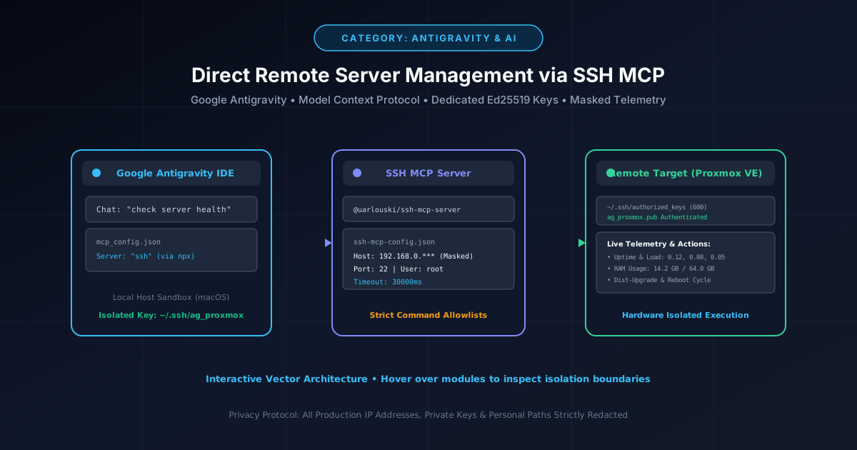
How to Give Google Antigravity Direct SSH Access to Remote Servers (Proxmox & Linux)
Connect Google Antigravity directly to Proxmox and Linux servers using the Model Context Protocol (MCP), dedicated Ed25519 keys, and automated updates.
By Md. Harun-Or-Roshid
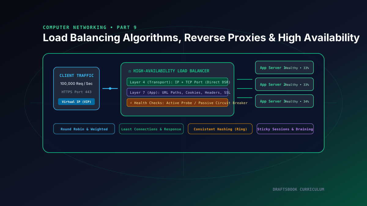
Part 9: Load Balancing: Layer 4 vs Layer 7, Algorithms, Reverse Proxies & High Availability
Master high-availability load balancing, comparing Layer 4 transport vs Layer 7 application routing, consistent hashing rings, and health checks.
By Md. Harun-Or-Roshid
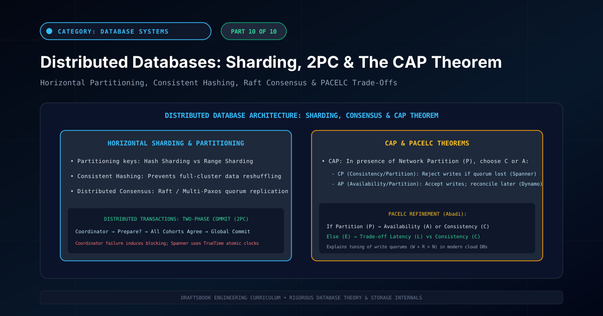
Part 10: Distributed Databases: Partitioning, Sharding, 2PC & CAP Theorem
Master distributed database architecture: horizontal sharding, consistent hashing, two-phase commit (2PC), CAP theorem trade-offs, and NewSQL engines.
By Md. Harun-Or-Roshid
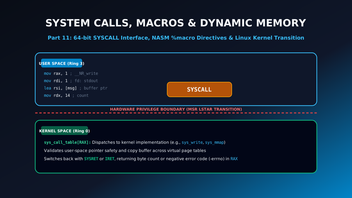
Part 11: Linux 64-Bit System Calls, NASM Macros & Dynamic Memory Allocation
Learn low-level systems programming: Linux 64-bit SYSCALL table, multi-argument NASM %macro directives, file I/O operations, and sys_mmap memory allocation.
By Md. Harun-Or-Roshid