Part 1: Interconnection Structures: System Buses, PCIe & Crossbar Switches
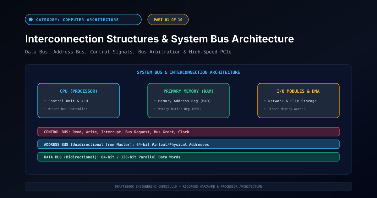
Series Overview & Learning Objectives
Welcome to Fundamentals of Computer Architecture & Organization, an exhaustive 10-part engineering curriculum dedicated to the physical organization, logical datapaths, pipelining, and memory hierarchies of modern computing processors. At its physical core, a computer system is a synchronized network of digital modules—processors, memory banks, and peripheral controllers—communicating over high-speed buses. In this opening installment, we analyze the physical and logical architectures of Interconnection Structures: examining data, address, and control buses, bus arbitration schemes, synchronous vs asynchronous clocking, and modern high-speed point-to-point interconnects such as PCI Express (PCIe).
1. Von Neumann Architecture & The Interconnection Problem
In 1945, mathematician John von Neumann formulated the stored-program architecture: programs and data reside together in a unified primary memory system. A computer consists of three fundamental hardware subsystems:
- Central Processing Unit (CPU): Contains the control unit, arithmetic logic unit (ALU), and internal general-purpose registers. It drives instructions and coordinates transfers.
- Primary Memory Subsystem (RAM): An array of linearly addressed memory cells storing opcodes and operational data operands.
- Input/Output (I/O) Subsystem: Secondary storage controllers (NVMe, SATA), network interface cards (NICs), and user human-interface devices.
To execute instructions, massive quantities of digital information must traverse these subsystems every clock cycle. The collection of physical conductive communication paths linking these functional units is designated as an Interconnection Structure.
2. System Bus Architecture: Data, Address & Control
A bus is a shared communication pathway consisting of multiple physical transmission lines. A 64-bit bus consists of 64 parallel micro-traces etched onto printed circuit boards (PCBs) or silicon substrates. System buses are partitioned into three functional signal groups:
1. Data Bus
Bidirectional parallel transmission lines.
Transfers actual data words between the CPU, memory, and peripheral controllers. The bus width (e.g. 32, 64, or 128 bits) directly dictates overall system data throughput per cycle.
2. Address Bus
Unidirectional lines driven by bus masters.
Identifies the source or destination memory address or I/O port. An $N$-bit address bus can directly reference $2^N$ discrete bytes. Modern 64-bit systems utilize 48-bit or 57-bit physical address lines, providing up to 4 Petabytes of physical addressability.
3. Control Bus
Coordinates timing and operational access.
Carries control signals including Memory Read, Memory Write, I/O Read, I/O Write, Bus Request, Bus Grant, Interrupt Request (IRQ), and system clock lines.
3. Bus Timing: Synchronous vs. Asynchronous Protocols
| Metric | Synchronous Bus Timing | Asynchronous Bus Timing |
|---|---|---|
| Clock Coordination | Events governed by a global master clock oscillation | No global clock; coordinates via handshaking signals |
| Handshake Protocol | Fixed cycle slots; devices must complete within clock period | Full four-phase handshake (REQ → ACK → REQ-LOW → ACK-LOW) |
| Device Heterogeneity | Limited by slowest peripheral device on the bus | Easily interfaces devices of drastically different speeds |
| Clock Skew Sensitivity | Severe over long physical traces at gigahertz frequencies | Immune to global clock skew; self-timed handshakes |
4. Bus Arbitration: Centralized vs. Distributed Schemes
When multiple bus masters (e.g. CPU Core 0, CPU Core 1, and high-speed DMA Network controllers) simultaneously request transmission over a shared bus, an arbitration protocol must resolve conflicting requests to prevent signal collisions:
- Daisy Chaining (Serial Centralized): A single Bus Grant signal line propagates serially through all requesting devices in prioritized order. The device physically closest to the bus controller receives priority. Drawback: susceptible to starvation for low-priority downstream devices.
- Independent Request (Parallel Centralized): Each master has a dedicated
Bus Request (BR)andBus Grant (BG)line connected directly to a central arbiter, which evaluates rotating round-robin or priority-encoded scheduling. - Distributed Self-Selection: Devices negotiate ownership autonomously across shared priority lines without a central arbiter (used in SCSI and CAN automotive buses).
5. Modern Evolution: From Shared Parallel Buses to Point-to-Point PCIe
Historically, motherboards utilized wide parallel shared buses (such as ISA, PCI, and PCI-X). However, as frequencies exceeded 133 MHz, parallel traces suffered from destructive trace length jitter, clock skew, and capacitive crosstalk.
Modern computer architectures have transitioned completely to serial point-to-point packet-switched interconnects, exemplified by PCI Express (PCIe 5.0 / 6.0), Intel Ultra Path Interconnect (UPI), and AMD Infinity Fabric. PCIe transmits high-speed data over dedicated point-to-point differential pairs ("lanes"), utilizing embedded 128b/130b clock encoding and PAM4 modulation to achieve bidirectional transfer rates exceeding 64 GB/second per x16 link.
Related reading
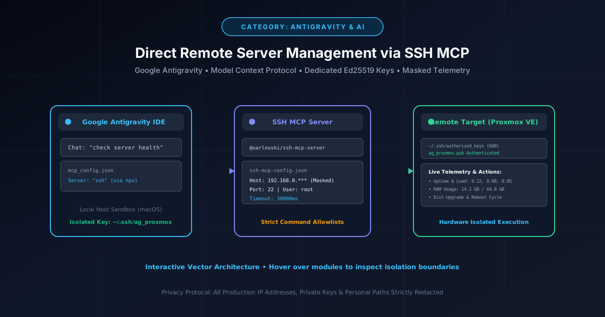
How to Give Google Antigravity Direct SSH Access to Remote Servers (Proxmox & Linux)
Connect Google Antigravity directly to Proxmox and Linux servers using the Model Context Protocol (MCP), dedicated Ed25519 keys, and automated updates.
By Md. Harun-Or-Roshid
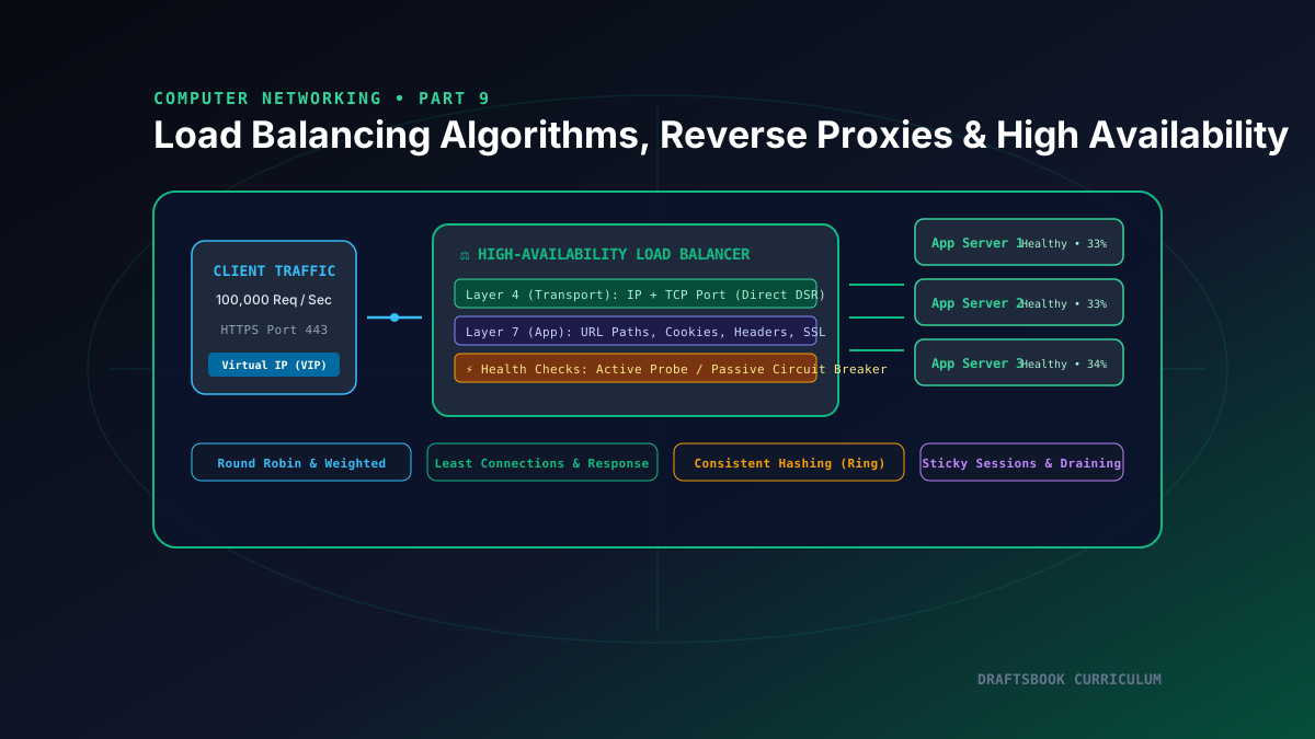
Part 9: Load Balancing: Layer 4 vs Layer 7, Algorithms, Reverse Proxies & High Availability
Master high-availability load balancing, comparing Layer 4 transport vs Layer 7 application routing, consistent hashing rings, and health checks.
By Md. Harun-Or-Roshid
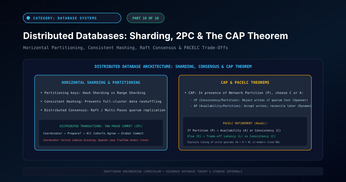
Part 10: Distributed Databases: Partitioning, Sharding, 2PC & CAP Theorem
Master distributed database architecture: horizontal sharding, consistent hashing, two-phase commit (2PC), CAP theorem trade-offs, and NewSQL engines.
By Md. Harun-Or-Roshid
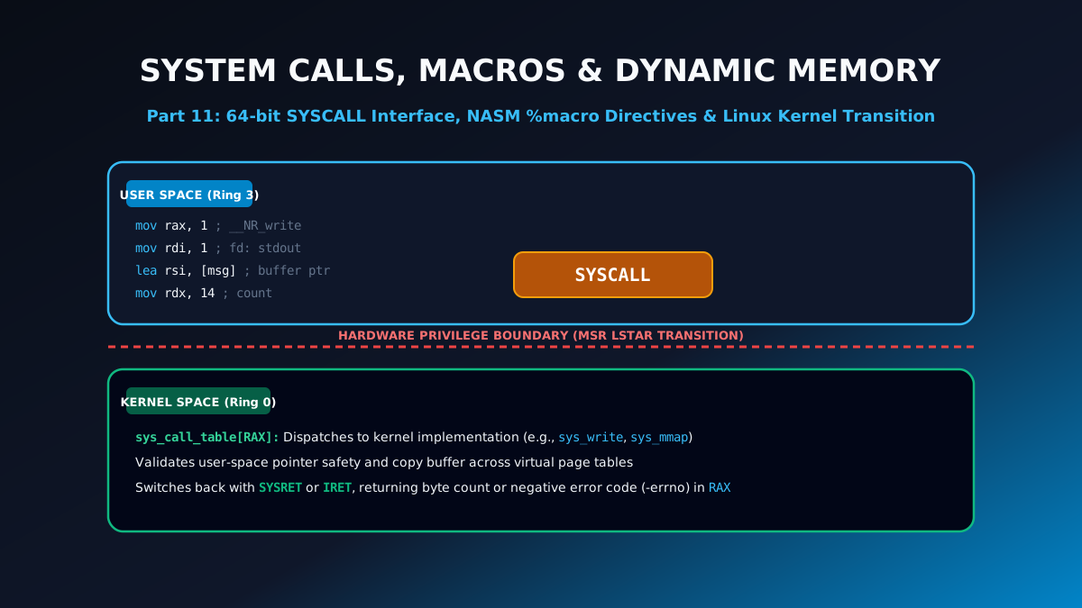
Part 11: Linux 64-Bit System Calls, NASM Macros & Dynamic Memory Allocation
Learn low-level systems programming: Linux 64-bit SYSCALL table, multi-argument NASM %macro directives, file I/O operations, and sys_mmap memory allocation.
By Md. Harun-Or-Roshid