Part 1: Display Devices: Raster Scan vs. Random Scan Display Architecture
Series Overview & Learning Objectives
Welcome to Fundamentals of Computer Graphics & Rendering Algorithms, an in-depth 11-part engineering curriculum dedicated to the mathematical, algorithmic, and architectural foundations of computer graphics. From early cathode-ray tube (CRT) display mechanisms to hardware-accelerated rasterization pipelines, computer graphics bridges continuous mathematical geometry and discrete pixel lattices. In this foundational article, we dissect the core hardware architectures of visual output devices: Raster Scan Displays and Random Scan (Vector) Displays, detailing framebuffer memory organization, electron beam deflection, refresh cycles, and their evolutionary legacy in modern GPU framebuffers.
1. Physical Principles of Cathode-Ray Tube (CRT) Displays
Before flat-panel OLED, mini-LED, and liquid crystal displays (LCD) became standard, graphical systems relied fundamentally on Cathode-Ray Tubes (CRTs). Inside a vacuum glass envelope, an electron gun emits a focused beam of high-velocity electrons accelerated by a high-voltage anode. The beam passes through horizontal and vertical deflection plates (electrostatic or electromagnetic coils) that direct the beam onto a glass faceplate coated with a microscopic layer of phosphorescent material.
When the kinetic energy of striking electrons impacts the phosphor crystals, the phosphor atoms enter an excited state and emit photons—a phenomenon known as fluorescence. As the electron beam departs, the light intensity decays exponentially—termed phosphorescence. The time required for emitted light to drop to 10% of its initial intensity is defined as the phosphor persistence. Because persistence is typically between 10 to 60 microseconds, an image must be redrawn continually at a high frequency (at least 60 Hz) to avoid visible human eye flicker—a biological limitation known as the Critical Flicker Fusion Frequency.
2. Raster Scan Display Architecture
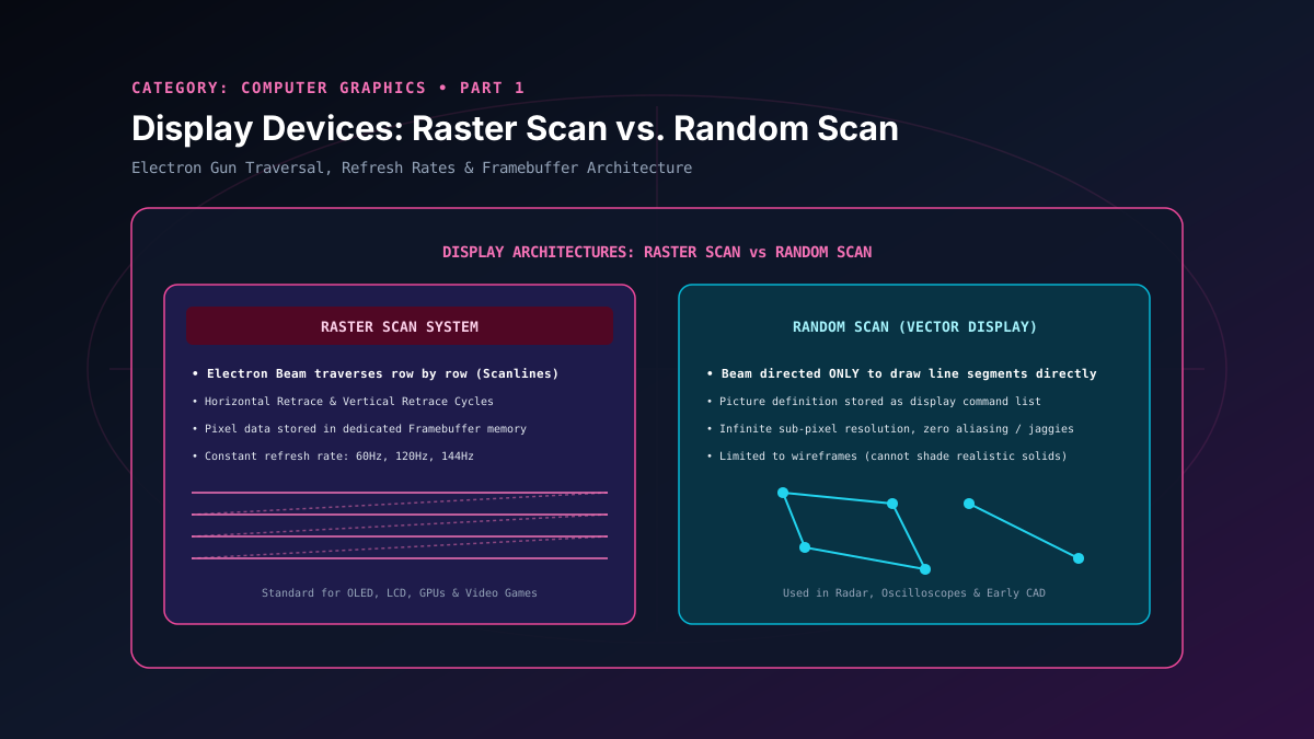
In a Raster Scan System, the electron beam sweeps across the entire screen row by row, moving from the top-left corner to the bottom-right corner in a strictly uniform rectangular grid. Each individual row of pixels is designated as a scan line.
Horizontal Retrace (H-Blank)
As the electron beam travels from left to right across a single scan line, its beam intensity is modulated to turn pixels on or off. Upon reaching the right edge, the beam is blanked (turned off) and rapidly deflected back to the left edge of the next lower scan line. This return interval is the Horizontal Retrace.
Vertical Retrace (V-Blank)
Once the electron beam finishes scanning the very bottom scan line of the screen, the beam is blanked and steered diagonally upwards back to the top-left corner to commence the next refresh frame. This interval is the Vertical Retrace (or VSync interval), historically leveraged by game developers for buffer swaps.
The Framebuffer (Refresh Buffer)
In raster systems, visual state is maintained in a dedicated region of memory known as the framebuffer or refresh buffer. Each address in the framebuffer maps directly to a discrete pixel coordinate $(x, y)$ on screen:
- 1-Bit Monochrome (Bitmap): 1 bit per pixel ($0 = \text{black}, 1 = \text{white}$). A screen resolution of $1920 \times 1080$ requires $1920 \times 1080 \times 1 \text{ bit} \approx 259.2 \text{ KB}$.
- 8-Bit Indexed Color: 8 bits per pixel (256 distinct palette entries mapped through a Color Look-Up Table / CLUT).
- 24-Bit / 32-Bit Truecolor (Pixmaps): 8 bits per channel (Red, Green, Blue, Alpha). An uncompressed 4K ($3840 \times 2160$) framebuffer requires $3840 \times 2160 \times 4 \text{ bytes} \approx 33.17 \text{ MB}$ per frame.
3. Random Scan (Vector / Calligraphic) Display Architecture
In a Random Scan Display (also referred to as a vector, stroke-writing, or calligraphic display), the electron beam does not scan systematically across inactive background space. Instead, the deflection coils steer the electron beam directly from endpoint to endpoint to draw line segments, exactly as a human draws with a pencil on paper.
The graphics processor executes a sequence of vector drawing instructions stored in a display buffer (or display file). For example, a command sequence might contain:
DRAW (450, 150)
DRAW (275, 400)
DRAW (100, 150)
The beam traverses only the edges of the specified triangle. Because the lines are drawn as continuous analog strokes rather than discrete pixel approximations, vector displays exhibit zero aliasing ("jaggies"), yielding pristine line smoothness. However, their major bottleneck is complexity: if a scene contains tens of thousands of lines, the refresh loop cannot revisit all lines before the phosphor decays, resulting in intolerable screen flickering. Furthermore, realistic filled polygon shading and photorealistic bitmap images cannot be rendered on pure vector systems.
4. Architectural Comparison: Raster Scan vs. Random Scan
| Characteristic | Raster Scan Display | Random Scan (Vector) Display |
|---|---|---|
| Beam Traversal | Sequential scan lines from top-to-bottom across entire screen | Arbitrary point-to-point lines directly tracing geometry |
| Memory Store | Framebuffer / Pixmap array (dimensions $W \times H$) | Display List / Display Command File |
| Resolution Limit | Bounded by framebuffer resolution and pixel grid spacing | Higher line resolution, bounded only by deflection coil precision |
| Aliasing (Jaggies) | Inherent staircasing on diagonal edges (requires antialiasing) | Zero aliasing; mathematically smooth continuous lines |
| Area Filling & Shading | Native support for filled polygons, textures, and bitmaps | Incapable of smooth shaded solid area fills |
| Refresh Rate Stability | Constant refresh rate (60/120/144 Hz) regardless of scene complexity | Variable refresh rate; flickers heavily when line count rises |
| Modern Applications | 100% of modern screens (OLED, LCD, GPU render buffers) | Air-traffic radar scopes, analog oscilloscopes, laser projectors |
5. The Modern Legacy: Double Buffering & VSync
In modern GPU architectures, raster scan principles endure in the form of double buffering and swapchains. If the GPU were to write directly to the active framebuffer being scanned by the display controller (the Front Buffer), the screen would exhibit jarring horizontal tears whenever a new frame is written mid-scan—a defect termed screen tearing.
To eliminate tearing, graphics systems utilize two distinct buffers in video memory (VRAM):
- Back Buffer: The GPU renders fragment shaders, primitives, and geometry into this off-screen buffer.
- Front Buffer: The display hardware reads pixel rows from this buffer and transmits them via DisplayPort/HDMI to the physical panel.
- Buffer Swap: During the vertical blanking interval (V-Blank), a pointer swap occurs instantaneously, swapping the Front and Back buffers without interrupting active scan lines.
Related reading
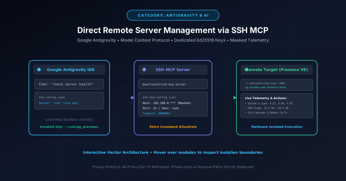
How to Give Google Antigravity Direct SSH Access to Remote Servers (Proxmox & Linux)
Connect Google Antigravity directly to Proxmox and Linux servers using the Model Context Protocol (MCP), dedicated Ed25519 keys, and automated updates.
By Md. Harun-Or-Roshid
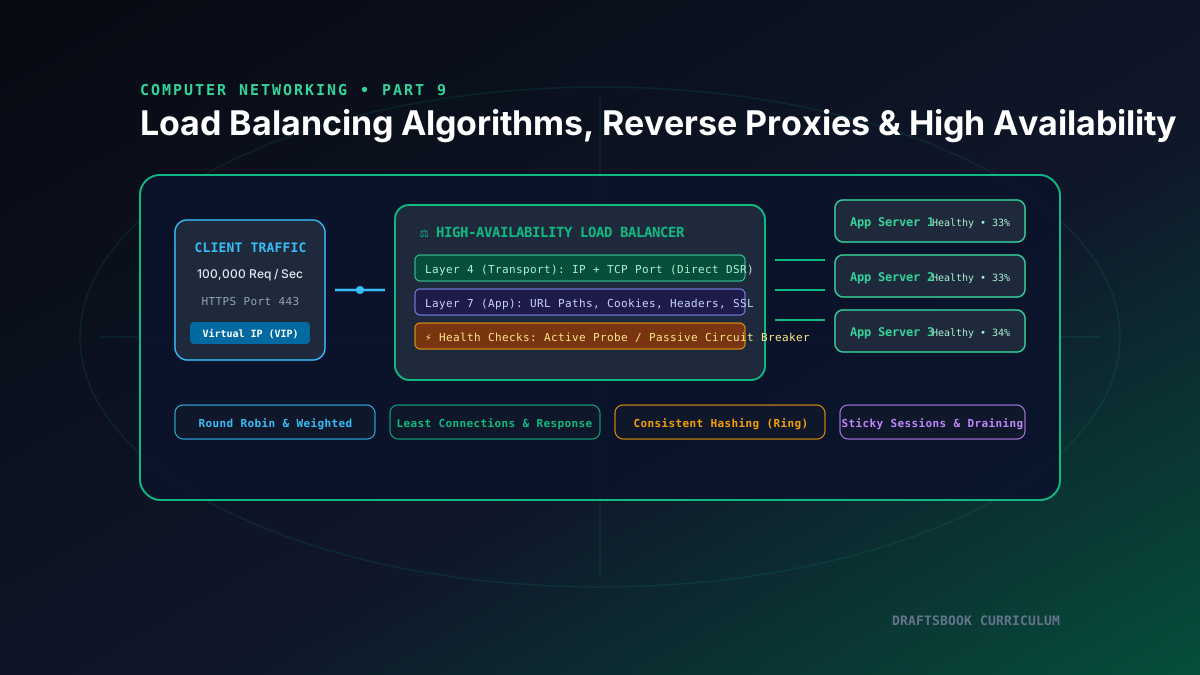
Part 9: Load Balancing: Layer 4 vs Layer 7, Algorithms, Reverse Proxies & High Availability
Master high-availability load balancing, comparing Layer 4 transport vs Layer 7 application routing, consistent hashing rings, and health checks.
By Md. Harun-Or-Roshid
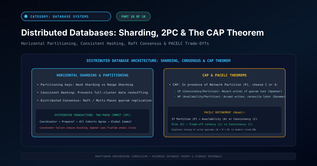
Part 10: Distributed Databases: Partitioning, Sharding, 2PC & CAP Theorem
Master distributed database architecture: horizontal sharding, consistent hashing, two-phase commit (2PC), CAP theorem trade-offs, and NewSQL engines.
By Md. Harun-Or-Roshid
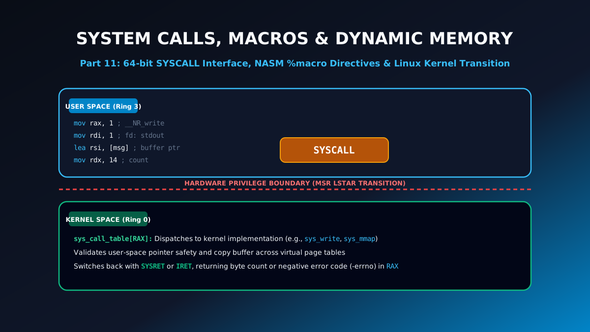
Part 11: Linux 64-Bit System Calls, NASM Macros & Dynamic Memory Allocation
Learn low-level systems programming: Linux 64-bit SYSCALL table, multi-argument NASM %macro directives, file I/O operations, and sys_mmap memory allocation.
By Md. Harun-Or-Roshid